8ZR-FXE FUEL FUEL PUMP INSTALLATION
PROCEDURE

 77020A
1.INSTALL FUEL SUCTION TUBE WITH PUMP AND GAUGE ASSEMBLY
77020A
1.INSTALL FUEL SUCTION TUBE WITH PUMP AND GAUGE ASSEMBLY
Install a new fuel suction tube set gasket to the fuel tank assembly.
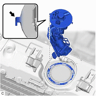
| *a | Protrusion |
| *b | Notch |
Set the fuel suction tube with pump and gauge assembly to the fuel tank assembly.
- NOTICE:
- ·
Be careful not to bend the arm of the fuel sender gauge assembly.
·Make sure the horizontal angle of the fuel suction plate sub-assembly is less than 90°.
·To avoid applying excessive force to the tip of the fuel sender gauge assembly, tilt the fuel sub-tank sub-assembly diagonally and insert it into the fuel tank assembly as shown in the illustration.
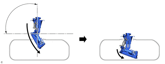 5.833,1.583 6.188,1.583 false 1.5,1.781 1.063,2 true 4.958,2.417 5.51,2.417 true 1.927,0.885 2.26,0.885 false 2.198,2.302 1.667,2.031 true 6.448,2.167 5.833,2.458 true 2.271,2.24 2.667,2.5 0.396,0.26 10 false *1 0.854,1.958 1.26,2.271 0.406,0.313 10 false *2 6.271,1.521 6.625,1.802 0.354,0.281 10 false *3 0.344,0.323 0.802,0.729 0.458,0.406 10 false *a 2.354,0.802 2.802,1.156 0.448,0.354 10 false *3 4.771,2.344 5.24,2.667 0.469,0.323 10 false *2 6.552,2.094 6.927,2.406 0.375,0.313 10 false *1
*1 Fuel Sender Gauge Assembly *2 Fuel Sub-tank Sub-assembly *3 Fuel Suction Plate Sub-assembly - - *a 90° - -
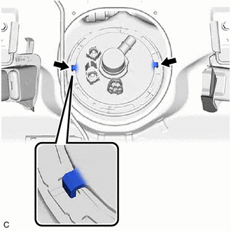
| *a | Protrusion |

|
Notch |
Align the protrusions of the fuel suction tube with pump and gauge assembly with the notches in the fuel tank assembly.
77144
2.INSTALL FUEL PUMP GAUGE RETAINER
Install the fuel pump gauge retainer.
While pressing down on the fuel suction tube with pump and gauge assembly, temporarily install the fuel pump gauge retainer.
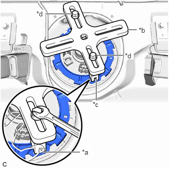
| *a | Insertion Point |
| *b | SST (Plate) |
| *c | SST (Claw) |
| *d | SST (Bolt) |
Temporarily install SST (plate) and SST (claw) to the fuel pump gauge retainer.
- SST
- 09808-01071
09808-14031 (09808-01030, 09808-01090)
- HINT:
-
Securely insert the ends of SST (claw) into the insertion points in the fuel pump gauge retainer.
While firmly pressing SST (claw) into the insertion points in the fuel pump gauge retainer, tighten SST (bolt).
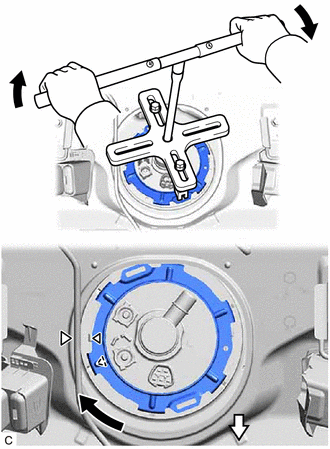
| *a | Triangle Mark (Fuel Pump Gauge Retainer) |
| *b | Triangle Mark (Fuel Tank Assembly) |
| *c | SST (Handle) |
| *d | SST (Plate) |
| *e | SST (Claw) |
| *f | SST (Bolt) |
| *g | Extension Bar |

|
Front Side |
Install SST (handle) and an extension bar to SST (plate).
- SST
- 09808-14031 (09808-01010)
Using SST, rotate the fuel pump gauge retainer so that the triangle mark on the fuel pump gauge retainer is aligned with the triangle mark on the fuel tank assembly to install the fuel suction tube with pump and gauge assembly to the fuel tank assembly.
- NOTICE:
- ·
Do not use any tools other than specified as this may result in damage to the fuel pump gauge retainer or fuel tank assembly.
·Do not press down on SST excessively as this may make the fuel pump gauge retainer hard to rotate, and may damage components.
·Make sure to rotate SST (handle) horizontally. If it is rotated at an angle, SST may come off.
·Do not spin SST too fast or use an impact wrench as this may result in damage to components.
·If SST comes off of the fuel pump gauge retainer, loosen SST (bolt) and reinstall SST.
·Make sure that the fuel suction tube set gasket does not come off.
Engage the claw to install the No. 1 fuel tube clamp.
77209F
3.CONNECT FUEL TANK MAIN TUBE SUB-ASSEMBLY
Push the fuel tube joint onto the plug of the fuel suction plate sub-assembly, then install the tube joint clip.
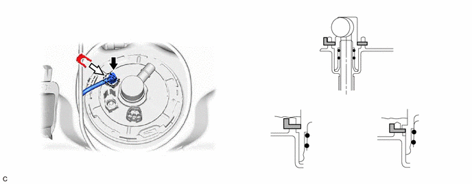
| *1 | Fuel Suction Plate Sub-assembly | *2 | Tube Joint Clip |
| *3 | Fuel Tank Main Tube Sub-assembly | - | - |
| *a | Fuel Tube Joint | *b | O-ring |
| *c | Correct | *d | Incorrect |
| *e | Collar | - | - |
|
|
Insert |
|
Insert |
- NOTICE:
- ·
Check that there are no scratches or foreign matter around the connecting parts of the fuel tube joint and plug before performing this work.
·Check that the fuel tube joint is securely inserted to the end.
·Check that the tube joint clip is on the collar of the fuel tube joint.
·After installing the tube joint clip, check that the fuel tank main tube sub-assembly is securely connected by pulling on it.
77404
4.CONNECT FUEL TANK VENT HOSE SUB-ASSEMBLY
Connect the fuel tank vent hose sub-assembly to the fuel suction tube with pump and gauge assembly.
89461
5.INSTALL FUEL TANK PRESSURE SENSOR (VAPOR PRESSURE SENSOR)
58325E
6.INSTALL REAR FLOOR SERVICE HOLE COVER
Remove any remaining butyl tape from the rear floor service hole cover and vehicle body.
Clean the installation surfaces of the rear floor service hole cover and vehicle body.
Connect the fuel suction tube with pump and gauge assembly connector and fuel tank pressure sensor (vapor pressure sensor) connector.
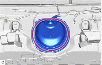
| *a | Butyl Tape Adhesion Area |
Install the rear floor service hole cover with new butyl tape.
- NOTICE:
-
Securely install the rear floor service hole cover.
82818E
7.INSTALL NO. 6 WIRING HARNESS PROTECTOR
Install a new No. 6 wiring harness protector to the rear floor service hole cover.
8.CONNECT CABLE TO NEGATIVE AUXILIARY BATTERY TERMINAL
9.INSPECT FOR FUEL LEAK
10.INSTALL REAR SEAT ASSEMBLY
for Fold Down Seat Type:
11.PERFORM INITIALIZATION
Perform "Inspection After Repair" after replacing the fuel pump.
12. INITIALIZATION AFTER RECONNECTING AUXILIARY BATTERY TERMINAL
- HINT:
-
When disconnecting and reconnecting the auxiliary battery, there is an automatic learning function that completes learning when the respective system is used.