HYBRID / BATTERY CONTROL PA10 HYBRID CONTROL SYSTEM(for LITHIUM-ION BATTERY) P05042B Brake Switch "A"/"B" Signal Cross Coupled
DESCRIPTION
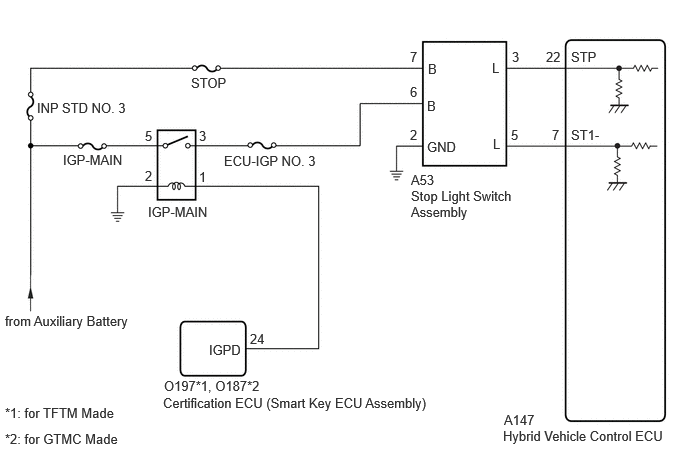
The stop light switch assembly is a duplex system that transmits two signals: STP and ST1-. These two signals are used by the hybrid vehicle control ECU to monitor whether or not the brake system is working properly. If the signals, which indicate the brake pedal is being depressed and released, are detected simultaneously, the hybrid vehicle control ECU interprets this as a malfunction in the stop light switch assembly and stores this DTC.
- HINT:
-
The normal signal conditions are as shown in the table below.
Signal (hybrid vehicle control ECU Terminal) Brake Pedal Released In Transition Brake Pedal Depressed STP OFF ON ON ST1- ON ON OFF
- ·
[OFF] denotes ground potential.
·[ON] denotes auxiliary battery potential (+B).
-
On the GTS, Data List item Stop Light SW is ON when the brake pedal is depressed.
| DTC No. | Detection Item | DTC Detection Condition | Trouble Area | MIL | Warning Indicate | Note |
|---|---|---|---|---|---|---|
| P05042B | Brake Switch "A"/"B" Signal Cross Coupled | Conditions (a) and (b) are met for 0.5 seconds or more (1 trip detection logic):
(a) Ignition switch ON (b) STP signal OFF when ST1- signal OFF |
·
Wire harness or connector ·
Stop light switch assembly ·
Hybrid vehicle control ECU |
Does not come on | Master Warning:
Does not come on |
SAE Code:
P0504 |
WIRING DIAGRAM
CAUTION / NOTICE / HINT
- NOTICE:
-
Inspect the fuses for circuits related to this system before performing the following procedure.
- HINT:
- ·
Stop light switch assembly conditions can be checked using the GTS.
(a)Enter the following menus: Powertrain / Hybrid Control / Data List / Stop Light SW.
(b)Check the Data List indication when the brake pedal is depressed and released.
Brake Pedal Operation Stop Light SW Depressed ON Released OFF
·Read Freeze Frame Data using the GTS. The ECM records vehicle and driving condition information as Freeze Frame Data the moment a DTC is stored. When troubleshooting, Freeze Frame Data can help determine if the vehicle was moving or stationary, if the engine was warmed up or not, if the air fuel ratio was lean or rich, and other data from the time the malfunction occurred.
PROCEDURE
Disconnect the stop light switch assembly connector.
Measure the voltage according to the value(s) in the table below.
- Standard Voltage:
Tester Connection Condition Specified Condition A53-7 (B) - Body ground Always 11 to 14 V
Reconnect the stop light switch assembly connector.
- Result:
Proceed to OK NG
OK
NG
Disconnect the stop light switch assembly connector.
Turn the ignition switch to ON.
Measure the voltage according to the value(s) in the table below.
- Standard Voltage:
Tester Connection Condition Specified Condition A53-6 (B) - Body ground Ignition switch ON 11 to 14 V
Turn the ignition switch off.
Reconnect the stop light switch assembly connector.
- Result:
Proceed to OK NG
OK
NG
Disconnect the stop light switch assembly connector.
Measure the resistance according to the value(s) in the table below.
- Standard Resistance:
Tester Connection Condition Specified Condition A53-2 (GND) - Body ground Always Below 1 Ω
Reconnect the stop light switch assembly connector.
- Result:
Proceed to OK NG
OK
NG
Disconnect the hybrid vehicle control ECU connector.
Turn the ignition switch to ON.
Measure the voltage according to the value(s) in the table below.
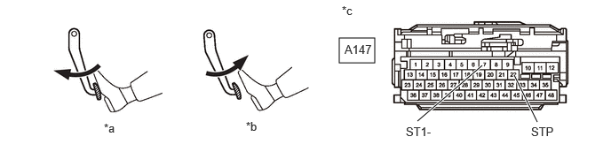
| *a | Brake Pedal Depressed | *b | Brake Pedal Released |
| *c | Front view of wire harness connector
(to Hybrid Vehicle Control ECU) |
- | - |
- Standard Voltage:
Tester Connection Brake Pedal Operation Specified Condition A147-7 (ST1-) - Body ground Released 7.5 to 14 V Depressed Below 1.5 V A147-22 (STP) - Body ground Released Below 1.5 V Depressed 7.5 to 14 V
Turn the ignition switch off.
Reconnect the hybrid vehicle control ECU connector.
- Result:
Proceed to OK NG
OK
NG
Disconnect the stop light switch assembly connector.
Disconnect the hybrid vehicle control ECU connector.
Measure the resistance according to the value(s) in the table below.
- Standard Resistance:
Tester Connection Condition Specified Condition A147-7 (ST1-) - A53-5 (L) Always Below 1 Ω A147-22 (STP) - A53-3 (L) Always Below 1 Ω A147-7 (ST1-) or A53-5 (L) - Body ground and other terminals Always 10 kΩ or higher A147-22 (STP) or A53-3 (L) - Body ground and other terminals Always 10 kΩ or higher
Reconnect the hybrid vehicle control ECU connector.
Reconnect the stop light switch assembly connector.
- Result:
Proceed to OK NG
OK
NG
Remove the IGP-MAIN relay from the No. 1 engine room relay block and No. 1 junction block assembly.
Disconnect the stop light switch assembly connector.
Measure the resistance according to the value(s) in the table below.
- Standard Resistance:
Tester Connection Condition Specified Condition 3 (IGP-MAIN relay holder) - A53-6 (B) Always Below 1 Ω 3 (IGP-MAIN relay holder) or A53-6 (B) - Body ground and other terminals Always 10 kΩ or higher
Reconnect the stop light switch assembly connector.
Install the IGP-MAIN relay.
- Result:
Proceed to OK NG
OK
NG