WINDOW / GLASS POWER WINDOW CONTROL SYSTEM(except NR Series Engine) TERMINALS OF ECU
CHECK POWER WINDOW REGULATOR MOTOR ASSEMBLY LH (for Driver Door)
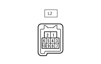
Disconnect the L2 power window regulator motor assembly LH (for driver door) connector.
Measure the voltage and resistance according to the value(s) in the table below.
- HINT:
-
Measure the values on the wire harness side with the connector disconnected.
| Terminal No. (Symbol) | Terminal Description | Condition | Specified Condition |
|---|---|---|---|
| L2-1 (GND) - Body ground | Ground | Always | Below 1 Ω |
| L2-2 (B) - Body ground | Power supply | Always*1
Ignition switch off*2 |
11 to 14 V |
*1: for Gasoline Model
*2: for HV Model
Reconnect the L2 power window regulator motor assembly LH (for driver door) connector.
Measure the voltage according to the value(s) in the table below.
| Terminal No. (Symbol) | Terminal Description | Condition | Specified Condition |
|---|---|---|---|
| L2-7 (DOWN) - L2-1 (GND) | Power window motor DOWN input | Ignition switch ON, multiplex network master switch assembly (driver door power window regulator switch) not pushed or not pulled | 11 to 14 V |
| Ignition switch ON, driver door power window moving, multiplex network master switch assembly (driver door power window regulator switch) pushed halfway down (Manual operation) | Below 1 V | ||
| Ignition switch ON, driver door power window fully closed | 11 to 14 V | ||
| Ignition switch ON, driver door power window moving, multiplex network master switch assembly (driver door power window regulator switch) fully pushed down (Auto operation) | Below 1 V | ||
| Ignition switch ON, driver door power window fully open | 11 to 14 V | ||
| L2-10 (UP) - L2-1 (GND) | Power window motor UP input | Ignition switch ON, multiplex network master switch assembly (driver door power window regulator switch) not pushed or not pulled | 11 to 14 V |
| Ignition switch ON, driver door power window moving, multiplex network master switch assembly (driver door power window regulator switch) pulled halfway up (Manual operation) | Below 1 V | ||
| Ignition switch ON, multiplex network master switch assembly (driver door power window regulator switch) fully open | 11 to 14 V | ||
| Ignition switch ON, driver door power window moving, multiplex network master switch assembly (driver door power window regulator switch) fully pulled up (Auto operation) | Below 1 V | ||
| Ignition switch ON, driver door power window fully closed | 11 to 14 V |
CHECK POWER WINDOW REGULATOR MOTOR ASSEMBLY RH (for Front Passenger Door)

Disconnect the K2 power window regulator motor assembly RH (for front passenger door) connector.
Measure the voltage and resistance according to the value(s) in the table below.
- HINT:
-
Measure the values on the wire harness side with the connector disconnected.
| Terminal No. (Symbol) | Terminal Description | Condition | Specified Condition |
|---|---|---|---|
| K2-1 (GND) - Body ground | Ground | Always | Below 1 Ω |
| K2-2 (B) - Body ground | Power supply | Always*1
Ignition switch off*2 |
11 to 14 V |
*1: for Gasoline Model
*2: for HV Model
Reconnect the K2 power window regulator motor assembly RH (for front passenger door) connector.
Measure the voltage according to the value(s) in the table below.
| Terminal No. (Symbol) | Terminal Description | Condition | Specified Condition |
|---|---|---|---|
| K2-4 (AUTO) - K2-1 (GND) | Power window motor AUTO UP input | Ignition switch ON, front passenger door power window fully open | 11 to 14 V |
| Ignition switch ON, front passenger door power window moving, power window regulator switch assembly fully pulled up (Auto operation) | Below 1 V | ||
| Ignition switch ON, front passenger door power window fully closed | 11 to 14 V | ||
| Power window motor AUTO DOWN input | Ignition switch ON, front passenger door power window fully closed | 11 to 14 V | |
| Ignition switch ON, front passenger door power window moving, power window regulator switch assembly fully pushed down (Auto operation) | Below 1 V | ||
| Ignition switch ON, front passenger door power window fully open | 11 to 14 V | ||
| K2-7 (DOWN) - K2-1 (GND) | Power window motor DOWN input | Ignition switch ON, power window regulator switch assembly not pushed or not pulled | 11 to 14 V |
| Ignition switch ON, front passenger door power window moving, power window regulator switch assembly pushed halfway down (Manual operation) | Below 1 V | ||
| Ignition switch ON, front passenger door power window fully closed | 11 to 14 V | ||
| Ignition switch ON, front passenger door power window moving, power window regulator switch assembly fully pushed down (Auto operation) | Below 1 V | ||
| Ignition switch ON, front passenger door power window fully open | 11 to 14 V | ||
| K2-10 (UP) - K2-1 (GND) | Power window motor UP input | Ignition switch ON, power window regulator switch assembly not pushed or not pulled | 11 to 14 V |
| Ignition switch ON, front passenger door power window moving, power window regulator switch assembly pulled halfway up (Manual operation) | Below 1 V | ||
| Ignition switch ON, front passenger door power window fully open | 11 to 14 V | ||
| Ignition switch ON, front passenger door power window moving, power window regulator switch assembly fully pulled up (Auto operation) | Below 1 V | ||
| Ignition switch ON, front passenger door power window fully closed | 11 to 14 V |
CHECK POWER WINDOW REGULATOR MOTOR ASSEMBLY LH (for Rear LH Door)
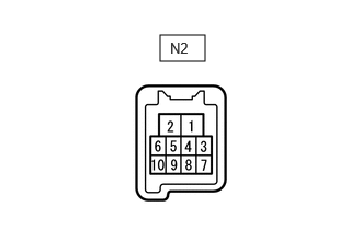
Disconnect the N2 power window regulator motor assembly LH (for rear LH door) connector.
Measure the voltage and resistance according to the value(s) in the table below.
- HINT:
-
Measure the values on the wire harness side with the connector disconnected.
| Terminal No. (Symbol) | Terminal Description | Condition | Specified Condition |
|---|---|---|---|
| N2-1 (GND) - Body ground | Ground | Always | Below 1 Ω |
| N2-2 (B) - Body ground | Power supply | Always*1
Ignition switch off*2 |
11 to 14 V |
*1: for Gasoline Model
*2: for HV Model
Reconnect the N2 power window regulator motor assembly LH (for rear LH door) connector.
Measure the voltage according to the value(s) in the table below.
| Terminal No. (Symbol) | Terminal Description | Condition | Specified Condition |
|---|---|---|---|
| N2-4 (AUTO) - N2-1 (GND) | Power window motor AUTO UP input | Ignition switch ON, rear LH door power window fully open | 11 to 14 V |
| Ignition switch ON, rear LH door power window moving, rear power window regulator switch assembly (for LH door) fully pulled up (Auto operation) | Below 1 V | ||
| Ignition switch ON, rear LH door power window fully closed | 11 to 14 V | ||
| Power window motor AUTO DOWN input | Ignition switch ON, rear LH door power window fully closed | 11 to 14 V | |
| Ignition switch ON, rear LH door power window moving, rear power window regulator switch assembly (for LH door) fully pushed down (Auto operation) | Below 1 V | ||
| Ignition switch ON, rear LH door power window fully open | 11 to 14 V | ||
| N2-7 (DOWN) - N2-1 (GND) | Power window motor DOWN input | Ignition switch ON, rear power window regulator switch assembly (for LH door) not pushed or not pulled | 11 to 14 V |
| Ignition switch ON, rear LH door power window moving, rear power window regulator switch assembly (for LH door) pushed halfway down (Manual operation) | Below 1 V | ||
| Ignition switch ON, rear LH door power window fully closed | 11 to 14 V | ||
| Ignition switch ON, rear LH door power window moving, rear power window regulator switch assembly (for LH door) fully pushed down (Auto operation) | Below 1 V | ||
| Ignition switch ON, rear LH door power window fully open | 11 to 14 V | ||
| N2-10 (UP) - N2-1 (GND) | Power window motor UP input | Ignition switch ON, rear power window regulator switch assembly (for LH door) not pushed or not pulled | 11 to 14 V |
| Ignition switch ON, rear LH door power window moving, rear power window regulator switch assembly (for LH door) pulled halfway up (Manual operation) | Below 1 V | ||
| Ignition switch ON, rear LH door power window fully open | 11 to 14 V | ||
| Ignition switch ON, rear LH door power window moving, rear power window regulator switch assembly (for LH door) fully pulled up (Auto operation) | Below 1 V | ||
| Ignition switch ON, rear LH door power window fully closed | 11 to 14 V |
CHECK POWER WINDOW REGULATOR MOTOR ASSEMBLY RH (for Rear RH Door)
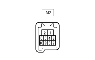
Disconnect the M2 power window regulator motor assembly RH (for rear RH door) connector.
Measure the voltage and resistance according to the value(s) in the table below.
- HINT:
-
Measure the values on the wire harness side with the connector disconnected.
| Terminal No. (Symbol) | Terminal Description | Condition | Specified Condition |
|---|---|---|---|
| M2-1 (GND) - Body ground | Ground | Always | Below 1 Ω |
| M2-2 (B) - Body ground | Power supply | Always*1
Ignition switch off*2 |
11 to 14 V |
*1: for Gasoline Model
*2: for HV Model
Reconnect the M2 power window regulator motor assembly RH (for rear RH door) connector.
Measure the voltage according to the value(s) in the table below.
| Terminal No. (Symbol) | Terminal Description | Condition | Specified Condition |
|---|---|---|---|
| M2-4 (AUTO) - M2-1 (GND) | Power window motor AUTO UP input | Ignition switch ON, rear RH door power window fully open | 11 to 14 V |
| Ignition switch ON, rear RH door power window moving, rear power window regulator switch assembly (for RH door) fully pulled up (Auto operation) | Below 1 V | ||
| Ignition switch ON, rear RH door power window fully closed | 11 to 14 V | ||
| Power window motor AUTO DOWN input | Ignition switch ON, rear RH door power window fully closed | 11 to 14 V | |
| Ignition switch ON, rear RH door power window moving, rear power window regulator switch assembly (for RH door) fully pushed down (Auto operation) | Below 1 V | ||
| Ignition switch ON, rear RH door power window fully open | 11 to 14 V | ||
| M2-7 (DOWN) - M2-1 (GND) | Power window motor DOWN input | Ignition switch ON, rear power window regulator switch assembly (for RH door) not pushed or not pulled | 11 to 14 V |
| Ignition switch ON, rear RH door power window moving, rear power window regulator switch assembly (for RH door) pushed halfway down (Manual operation) | Below 1 V | ||
| Ignition switch ON, rear RH door power window fully closed | 11 to 14 V | ||
| Ignition switch ON, rear RH door power window moving, rear power window regulator switch assembly (for RH door) fully pushed down (Auto operation) | Below 1 V | ||
| Ignition switch ON, rear RH door power window fully open | 11 to 14 V | ||
| M2-10 (UP) - M2-1 (GND) | Power window motor UP input | Ignition switch ON, rear power window regulator switch assembly (for RH door) not pushed or not pulled | 11 to 14 V |
| Ignition switch ON, rear RH door power window moving, rear power window regulator switch assembly (for RH door) pulled halfway up (Manual operation) | Below 1 V | ||
| Ignition switch ON, rear RH door power window fully open | 11 to 14 V | ||
| Ignition switch ON, rear RH door power window moving, rear power window regulator switch assembly (for RH door) fully pulled up (Auto operation) | Below 1 V | ||
| Ignition switch ON, rear RH door power window fully closed | 11 to 14 V |
CHECK MULTIPLEX NETWORK MASTER SWITCH ASSEMBLY
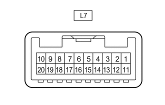
Disconnect the L7 multiplex network master switch assembly connector.
Measure the voltage and resistance according to the value(s) in the table below.
- HINT:
-
Measure the values on the wire harness side with the connector disconnected.
| Terminal No. (Symbol) | Terminal Description | Condition | Specified Condition |
|---|---|---|---|
| L7-11 (B) - L7-12 (GND) | Power supply | Always*1
Ignition switch off*2 |
11 to 14 V |
| L7-12 (GND) - Body ground | Ground | Always | Below 1 Ω |
*1: for Gasoline Model
*2: for HV Model
Reconnect the L7 multiplex network master switch assembly connector.
Measure the voltage according to the value(s) in the table below.
| Terminal No. (Symbol) | Terminal Description | Condition | Specified Condition |
|---|---|---|---|
| L7-15 (DOWN) - L7-12 (GND) | Power window motor DOWN output | Ignition switch ON, driver door power window regulator switch not pushed or not pulled | 11 to 14 V |
| Ignition switch ON, driver door power window moving, driver door power window regulator switch pushed halfway down (Manual operation) | Below 1 V | ||
| L7-20 (UP) - L7-12 (GND) | Power window motor UP output | Ignition switch ON, driver door power window regulator switch not pushed or not pulled | 11 to 14 V |
| Ignition switch ON, driver door power window moving, driver door power window regulator switch pulled halfway up (Manual operation) | Below 1 V |
CHECK POWER WINDOW REGULATOR SWITCH ASSEMBLY

Disconnect the K12 power window regulator switch assembly connector.
Measure the resistance according to the value(s) in the table below.
- HINT:
-
Measure the values on the wire harness side with the connector disconnected.
| Terminal No. (Symbol) | Terminal Description | Condition | Specified Condition |
|---|---|---|---|
| K12-7 (GND) - Body ground | Ground | Always | Below 1 Ω |
Reconnect the K12 power window regulator switch assembly connector.
Measure the voltage according to the value(s) in the table below.
| Terminal No. (Symbol) | Terminal Description | Condition | Specified Condition |
|---|---|---|---|
| K12-5 (UP) - K12-7 (GND) | Power window motor UP output | Ignition switch ON, power window regulator switch assembly not pushed or not pulled | 11 to 14 V |
| Ignition switch ON, front passenger door power window moving, power window regulator switch assembly pulled halfway up (Manual operation) | Below 1 V | ||
| Ignition switch ON, front passenger door power window fully open | 11 to 14 V | ||
| Ignition switch ON, front passenger door power window moving, power window regulator switch assembly fully pulled up (Auto operation) | Below 1 V | ||
| Ignition switch ON, front passenger door power window fully closed | 11 to 14 V | ||
| K12-4 (DOWN) - K12-7 (GND) | Power window motor DOWN output | Ignition switch ON, power window regulator switch assembly not pushed or not pulled | 11 to 14 V |
| Ignition switch ON, front passenger door power window moving, power window regulator switch assembly pushed halfway down (Manual operation) | Below 1 V | ||
| Ignition switch ON, front passenger door power window fully closed | 11 to 14 V | ||
| Ignition switch ON, front passenger door power window moving, power window regulator switch assembly fully pushed down (Auto operation) | Below 1 V | ||
| Ignition switch ON, front passenger door power window fully open | 11 to 14 V | ||
| K12-8 (AUTO) - K12-7 (GND) | Power window motor AUTO UP output | Ignition switch ON, front passenger door power window fully open | 11 to 14 V |
| Ignition switch ON, front passenger door power window moving, power window regulator switch assembly fully pulled up (Auto operation) | Below 1 V | ||
| Ignition switch ON, front passenger door power window fully closed | 11 to 14 V | ||
| Power window motor AUTO DOWN output | Ignition switch ON, front passenger door power window fully closed | 11 to 14 V | |
| Ignition switch ON, front passenger door power window moving, power window regulator switch assembly fully pushed down (Auto operation) | Below 1 V | ||
| Ignition switch ON, front passenger door power window fully open | 11 to 14 V |
CHECK REAR POWER WINDOW REGULATOR SWITCH ASSEMBLY (for LH Door)
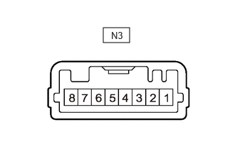
Disconnect the N3 rear power window regulator switch assembly (for LH door) connector.
Measure the resistance according to the value(s) in the table below.
- HINT:
-
Measure the values on the wire harness side with the connector disconnected.
| Terminal No. (Symbol) | Terminal Description | Condition | Specified Condition |
|---|---|---|---|
| N3-7 (GND) - Body ground | Ground | Always | Below 1 Ω |
Reconnect the N3 rear power window regulator switch assembly (for LH door) connector.
Measure the voltage according to the value(s) in the table below.
| Terminal No. (Symbol) | Terminal Description | Condition | Specified Condition |
|---|---|---|---|
| N3-5 (UP) - N3-7 (GND) | Power window motor UP output | Ignition switch ON, rear power window regulator switch assembly (for LH door) not pushed or not pulled | 11 to 14 V |
| Ignition switch ON, rear LH door power window moving, rear power window regulator switch assembly (for LH door) pulled halfway up (Manual operation) | Below 1 V | ||
| Ignition switch ON, rear LH door power window fully open | 11 to 14 V | ||
| Ignition switch ON, rear LH door power window moving, rear power window regulator switch assembly (for LH door) fully pulled up (Auto operation) | Below 1 V | ||
| Ignition switch ON, rear LH door power window fully closed | 11 to 14 V | ||
| N3-4 (DOWN) - N3-7 (GND) | Power window motor DOWN output | Ignition switch ON, rear power window regulator switch assembly (for LH door) not pushed or not pulled | 11 to 14 V |
| Ignition switch ON, rear LH door power window moving, rear power window regulator switch assembly (for LH door) pushed halfway down (Manual operation) | Below 1 V | ||
| Ignition switch ON, rear LH door power window fully closed | 11 to 14 V | ||
| Ignition switch ON, rear LH door power window moving, rear power window regulator switch assembly (for LH door) fully pushed down (Auto operation) | Below 1 V | ||
| Ignition switch ON, rear LH door power window fully open | 11 to 14 V | ||
| N3-8 (AUTO) - N3-7 (GND) | Power window motor AUTO UP output | Ignition switch ON, rear LH door power window fully open | 11 to 14 V |
| Ignition switch ON, rear LH door power window moving, rear power window regulator switch assembly (for LH door) fully pulled up (Auto operation) | Below 1 V | ||
| Ignition switch ON, rear LH door power window fully closed | 11 to 14 V | ||
| Power window motor AUTO DOWN output | Ignition switch ON, rear LH door power window fully closed | 11 to 14 V | |
| Ignition switch ON, rear LH door power window moving, rear power window regulator switch assembly (for LH door) fully pushed down (Auto operation) | Below 1 V | ||
| Ignition switch ON, rear LH door power window fully open | 11 to 14 V |
CHECK REAR POWER WINDOW REGULATOR SWITCH ASSEMBLY (for RH Door)
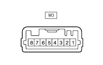
Disconnect the M3 rear power window regulator switch assembly (for RH door) connector.
Measure the resistance according to the value(s) in the table below.
- HINT:
-
Measure the values on the wire harness side with the connector disconnected.
| Terminal No. (Symbol) | Terminal Description | Condition | Specified Condition |
|---|---|---|---|
| M3-7 (GND) - Body ground | Ground | Always | Below 1 Ω |
Reconnect the M3 rear power window regulator switch assembly (for RH door) connector.
Measure the voltage according to the value(s) in the table below.
| Terminal No. (Symbol) | Terminal Description | Condition | Specified Condition |
|---|---|---|---|
| M3-5 (UP) - M3-7 (GND) | Power window motor UP output | Ignition switch ON, rear power window regulator switch assembly (for RH door) not pushed or not pulled | 11 to 14 V |
| Ignition switch ON, rear RH door power window moving, rear power window regulator switch assembly (for RH door) pulled halfway up (Manual operation) | Below 1 V | ||
| Ignition switch ON, rear RH door power window fully open | 11 to 14 V | ||
| Ignition switch ON, rear RH door power window moving, rear power window regulator switch assembly (for RH door) fully pulled up (Auto operation) | Below 1 V | ||
| Ignition switch ON, rear RH door power window fully closed | 11 to 14 V | ||
| M3-4 (DOWN) - M3-7 (GND) | Power window motor DOWN output | Ignition switch ON, rear power window regulator switch assembly (for RH door) not pushed or not pulled | 11 to 14 V |
| Ignition switch ON, rear RH door power window moving, rear power window regulator switch assembly (for RH door) pushed halfway down (Manual operation) | Below 1 V | ||
| Ignition switch ON, rear RH door power window fully closed | 11 to 14 V | ||
| Ignition switch ON, rear RH door power window moving, rear power window regulator switch assembly (for RH door) fully pushed down (Auto operation) | Below 1 V | ||
| Ignition switch ON, rear RH door power window fully open | 11 to 14 V | ||
| M3-8 (AUTO) - M3-7 (GND) | Power window motor AUTO UP output | Ignition switch ON, rear RH door power window fully open | 11 to 14 V |
| Ignition switch ON, rear RH door power window moving, rear power window regulator switch assembly (for RH door) fully pulled up (Auto operation) | Below 1 V | ||
| Ignition switch ON, rear RH door power window fully closed | 11 to 14 V | ||
| Power window motor AUTO DOWN output | Ignition switch ON, rear RH door power window fully closed | 11 to 14 V | |
| Ignition switch ON, rear RH door power window moving, rear power window regulator switch assembly (for RH door) fully pushed down (Auto operation) | Below 1 V | ||
| Ignition switch ON, rear RH door power window fully open | 11 to 14 V |
CHECK POWER DISTRIBUTION BOX ASSEMBLY AND MAIN BODY ECU (MULTIPLEX NETWORK BODY ECU)
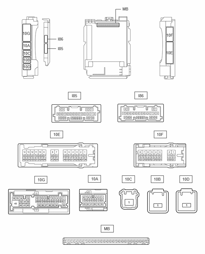
Remove the main body ECU (multiplex network body ECU) from the power distribution box assembly.
Reconnect the power distribution box assembly connectors.
Measure the voltage and resistance according to the value(s) in the table below.
- HINT:
-
Measure the values on the wire harness side with the connectors connected.
| Terminal No. (Symbol) | Terminal Description | Condition | Specified Condition |
|---|---|---|---|
| MB-13 (GND1) - Body ground | Ground | Always | Below 1 Ω |
| MB-14 (GND2) - Body ground | Ground | Always | Below 1 Ω |
| MB-26 (BECU) - Body ground | Auxiliary battery power supply | Always*1
Ignition switch off*2 |
11 to 14 V |
| MB-27 (IGR) - Body ground | IG power supply | Ignition switch ON | 11 to 14 V |
| Ignition switch off | Below 1 V |
*1: for Gasoline Model
*2: for HV Model
Reconnect the MB main body ECU (multiplex network body ECU) connector.
Check for voltage and check pulses according to the value(s) in the table below.
| Terminal No. (Symbol) | Terminal Description | Condition | Specified Condition |
|---|---|---|---|
| 10G-22 (FRCY) - Body ground | Front door courtesy light switch (for RH) input | Front door RH open → closed | Below 1 V → 11 to 14 V or pulse output (maximum 14 V)* |
| 10G-23 (FLCY) - Body ground | Front door courtesy light switch (for LH) input | Front door LH open → closed | Below 1 V → 11 to 14 V or pulse output (maximum 14 V)* |
| 10E-15 - Body ground | LIN communication line | Ignition switch ON | Pulse generation |
| I85-28 (L2) - Body ground | Driver door key-linked lock input | Driver door key cylinder turned to lock | Below 1 V |
| Driver door key cylinder not turned | Pulse generation | ||
| I85-4 (UL3) - Body ground | Driver door key-linked unlock input | Driver door key cylinder turned to unlock | Below 1 V |
| Driver door key cylinder not turned | Pulse generation |
*: Differs depending on the vehicle model