LIGHTING (EXT) LIGHTING SYSTEM(except NR Series Engine) Headlight Dimmer Switch Circuit
DESCRIPTION
The steering sensor receives the following switch information:
Light control switch in tail, head or AUTO position
Dimmer switch in high, low or high flash (pass) position
Fog light switch in front*, rear or off position
*: w/ Front Fog Light
WIRING DIAGRAM
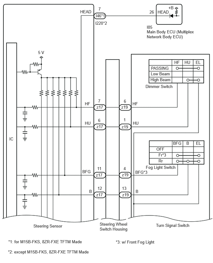
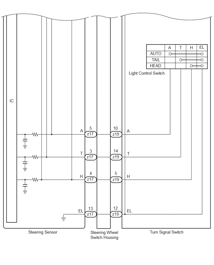
CAUTION / NOTICE / HINT
- NOTICE:
-
Before replacing the main body ECU (multiplex network body ECU), refer to Service Bulletin.
PROCEDURE
Read the Data List according to the display on the GTS.
- Chassis > Steering Angle Sensor > Data List
-
Tester Display Measurement Item Normal Condition Reference Value Diagnostic Note Auto Light Switch Light control switch AUTO position signal OFF or ON OFF: Light control switch not in AUTO position
ON: Light control switch in AUTO position- Head Light Switch (Tail) Light control switch tail position signal OFF or ON OFF: Light control switch in neither tail nor head position
ON: Light control switch in tail or head position- Head Light Switch (Head) Light control switch head position signal OFF or ON OFF: Light control switch not in head position
ON: Light control switch in head position- High Beam Main Switch Dimmer switch high position signal OFF or ON OFF: Dimmer switch not in high position
ON: Dimmer switch in high position- Passing Light Switch Dimmer switch high flash position (pass) signal OFF or ON OFF: Dimmer switch not in high flash position
ON: Dimmer switch in high flash position- Front Fog Light Switch Front fog light switch signal OFF or ON OFF: Front fog light switch off
ON: Front fog light switch onw/ Front Fog Light Rear Fog Light/Bad Weather Switch Rear fog light switch signal OFF or ON OFF: Rear fog light switch off
ON: Rear fog light switch on-
- Chassis > Steering Angle Sensor > Data List
-
Tester Display Auto Light Switch Head Light Switch (Tail) Head Light Switch (Head) High Beam Main Switch Passing Light Switch Front Fog Light Switch Rear Fog Light/Bad Weather Switch - 50003 445 4,5,6,7,8,13,14
- OK:
Normal conditions listed above are displayed.
- Result:
Proceed to OK NG
OK
NG
Read the Data List according to the display on the GTS.
- Body Electrical > Main Body > Data List
-
Tester Display Measurement Item Normal Condition Reference Value Diagnostic Note Light Control Switch (HEAD) Light control switch head position signal OFF or ON OFF: Light control switch not in head position
ON: Light control switch in head position-
- Body Electrical > Main Body > Data List
-
Tester Display Light Control Switch (HEAD) - 50003 449 108
- OK:
Normal conditions listed above are displayed.
- Result:
Proceed to OK NG
OK
NG
Remove the steering sensor.
for M15B-FKS, 8ZR-FXE TFTM Made
Measure the resistance according to the value(s) in the table below.
- Standard Resistance:
Tester Connection Condition Specified Condition I46-7 (HEAD) - z17-4 (H) Always Below 1 Ω
except M15B-FKS, 8ZR-FXE TFTM Made
Measure the resistance according to the value(s) in the table below.
- Standard Resistance:
Tester Connection Condition Specified Condition I220-7 (HEAD) - z17-4 (H) Always Below 1 Ω
- Result:
Proceed to OK NG
OK
NG
Disconnect the I85 main body ECU (multiplex network body ECU) connector.
for M15B-FKS, 8ZR-FXE TFTM Made
Measure the resistance according to the value(s) in the table below.
- Standard Resistance:
Tester Connection Condition Specified Condition I46-7 (HEAD) - I85-26 (HEAD) Always Below 1 Ω I46-7 (HEAD) or I85-26 (HEAD) - Body ground Always 10 kΩ or higher
except M15B-FKS, 8ZR-FXE TFTM Made
Measure the resistance according to the value(s) in the table below.
- Standard Resistance:
Tester Connection Condition Specified Condition I220-7 (HEAD) - I85-26 (HEAD) Always Below 1 Ω I220-7 (HEAD) or I85-26 (HEAD) - Body ground Always 10 kΩ or higher
- Result:
Proceed to OK NG
OK
NG
- Result:
Proceed to OK NG
OK
NG
- Result:
Proceed to OK NG
OK
NG