RM3660EC
_55
Steering
_080761
POWER ASSIST SYSTEMS
_0392075
POWER STEERING SYSTEM(for HV Model)
C
POWER ASSIST SYSTEMS POWER STEERING SYSTEM(for HV Model) C123A17 Supply Voltage Circuit Circuit Voltage Above Threshold
DESCRIPTION
The power steering ECU assembly distinguishes the power switch status as on (IG) or off through the IG power source circuit.
| DTC No. | Detection Item | DTC Detection Condition | Trouble Area | Warning Indicate | Return-to-normal Condition | Note |
|---|---|---|---|---|---|---|
| C123A17 | Supply Voltage Circuit Circuit Voltage Above Threshold | IG voltage is 18.5 V or more | ·
EPS-IGR fuse ·
IG power source circuit ·
Power steering ECU assembly |
EPS warning light: Comes on | The ECU judges the system has returned to normal or the power switch is turned on (IG) again | - |
WIRING DIAGRAM

5.438,2.823 6.76,3.24
1.323,0.417
10
false
Power Steering ECU Assembly
3.708,0.875 4.438,1.104
0.729,0.229
10
false
EPS-IGR
5.323,0.708 5.563,0.906
0.24,0.198
10
false
I21
5.323,1.896 5.677,2.115
0.354,0.219
10
false
I42
5.385,0.521 5.823,0.823
0.438,0.302
10
false
1
5.667,0.708 6.104,1.01
0.438,0.302
10
false
IG
5.656,1.896 6.094,2.083
0.438,0.188
10
false
PGND
5.385,1.708 5.823,2.01
0.438,0.302
10
false
2
1.427,0.719 2.99,1.104
1.563,0.385
10
false
from IGR NO. 2 Relay
CAUTION / NOTICE / HINT
- NOTICE:
-
Inspect the fuses for circuits related to this system before performing the following procedure.
PROCEDURE
1.CHECK HARNESS AND CONNECTOR (AUXILIARY BATTERY - POWER STEERING ECU ASSEMBLY)
a.
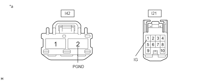
Disconnect the I42 and I21 power steering ECU assembly connectors.
2.094,0.344 2.542,0.583
0.448,0.24
5.083,0.344 5.531,0.583
0.448,0.24
4.646,1.938 5.031,1.375
false
2.667,2.167 2.667,1.625
false
0.323,0.135 0.635,0.292
0.313,0.156
10
false
*a
2.219,0.375 2.75,0.667
0.531,0.292
10
false
I42
5.188,0.375 5.719,0.667
0.531,0.292
10
false
I21
2.49,2.219 3.021,2.51
0.531,0.292
10
false
PGND
4.583,1.979 5.115,2.271
0.531,0.292
10
false
IG
| *a | Front view of wire harness connector
(to Power Steering ECU Assembly) |
- | - |
b.
Measure the voltage according to the value(s) in the table below.
- Standard Voltage:
Tester Connection Condition Specified Condition I21-1 (IG) - Body ground Power switch on (IG) 8 to 16 V
c.
Measure the resistance according to the value(s) in the table below.
- Standard Resistance:
Tester Connection Condition Specified Condition I42-2 (PGND) - Body ground Always Below 1 Ω
- Result:
Proceed to OK NG
OK
REPLACE POWER STEERING ECU ASSEMBLY
NG
REPAIR OR REPLACE HARNESS OR CONNECTOR