☰ Toyota Levin Hybrid☰ فهرستEngine / Hybrid System › HYBRID / BATTERY CONTROL › HV RELAY ASSEMBLY(for LITHIUM-ION BATTERY)
RM3660EC
_51
Engine / Hybrid System
_080773
HYBRID / BATTERY CONTROL
_0599560
HV RELAY ASSEMBLY(for LITHIUM-ION BATTERY)
G
HYBRID / BATTERY CONTROL HV RELAY ASSEMBLY(for LITHIUM-ION BATTERY) INSPECTION
PROCEDURE

 G92Z0
1.INSPECT HV BATTERY JUNCTION BLOCK ASSEMBLY
G92Z0
1.INSPECT HV BATTERY JUNCTION BLOCK ASSEMBLY
a.
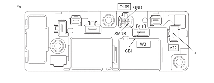
Inspect SMRB:
i.
Measure the resistance according to the value(s) in the table below.
3.948,0.115 4.375,0.333
0.427,0.219
5.635,1.51 5.979,1.719
0.344,0.208
4.583,1.385 5.031,1.604
0.448,0.219
4.24,0.625 4.573,0.313
true
4.052,1.031 4.292,0.802
true
4.698,1.063 4.323,1.583
true
6.458,1.698 5.802,1.125
true
0.573,0.146 0.885,0.302
0.313,0.156
10
false
*a
4,0.146 4.458,0.344
0.458,0.198
10
false
O169
4.458,0.167 4.792,0.375
0.333,0.208
10
false
GND
3.833,1.052 4.26,1.208
0.427,0.156
10
true
SMRB
5.698,1.531 5.99,1.719
0.292,0.188
10
false
z22
6.5,1.708 6.656,1.906
0.156,0.198
10
false
+
4.688,1.406 5.063,1.594
0.375,0.188
10
false
W3
4.188,1.635 4.438,1.833
0.25,0.198
10
false
CBI
| *a | Component without harness connected
(HV Battery Junction Block Assembly) |
- | - |
- Standard Resistance:
Tester Connection Condition Specified Condition z22-1 (+) - W3-1 (CBI) Auxiliary battery voltage not applied between terminals O169-4 (SMRB) and O169-2 (GND) 10 kΩ or higher Auxiliary battery voltage applied between terminals O169-4 (SMRB) and O169-2 (GND) Below 1 Ω
ii.
Measure the resistance according to the value(s) in the table below.
- Standard Resistance:
Tester Connection Condition Specified Condition O169-4 (SMRB) - O169-2 (GND) -40 to 80°C (-40 to 176°F) 20.6 to 40.8 Ω
If the result is not as specified, replace the HV battery junction block assembly.
b.
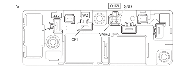
Inspect SMRG:
i.
Measure the resistance according to the value(s) in the table below.
3.969,0.115 4.396,0.323
0.427,0.208
1.885,0.479 2.25,0.656
0.365,0.177
2.969,0.448 3.271,0.667
0.302,0.219
3.802,1.146 4.115,0.792
true
4.615,0.302 4.24,0.688
true
2.74,1.344 3.073,0.958
true
1.542,1.135 2.052,0.938
true
0.573,0.146 0.885,0.302
0.313,0.156
10
false
*a
4.021,0.135 4.479,0.333
0.458,0.198
10
false
O169
4.521,0.156 4.854,0.302
0.333,0.146
10
true
GND
3.625,1.177 4.073,1.375
0.448,0.198
10
true
SMRG
3.01,0.479 3.333,0.656
0.323,0.177
10
false
W2
1.958,0.479 2.292,0.635
0.333,0.156
10
false
z23
2.615,1.375 2.99,1.583
0.375,0.208
10
false
CEI
1.417,1.115 1.573,1.313
0.156,0.198
10
false
-
| *a | Component without harness connected
(HV Battery Junction Block Assembly) |
- | - |
- Standard Resistance:
Tester Connection Condition Specified Condition z23-1 (-) - W2-1 (CEI) Auxiliary battery voltage not applied between terminals O169-6 (SMRG) and O169-2 (GND) 10 kΩ or higher Auxiliary battery voltage applied between terminals O169-6 (SMRG) and O169-2 (GND) Below 1 Ω
ii.
Measure the resistance according to the value(s) in the table below.
- Standard Resistance:
Tester Connection Condition Specified Condition O169-6 (SMRG) - O169-2 (GND) -40 to 80°C (-40 to 176°F) 20.6 to 40.8 Ω
If the result is not as specified, replace the HV battery junction block assembly.