☰ Toyota Levin Hybrid☰ فهرستAudio / Visual / Telematics › TELEMATICS › TELEMATICS SYSTEM(for HV Model)
RM3660EC
_56
Audio / Visual / Telematics
_080753
TELEMATICS
_0391552
TELEMATICS SYSTEM(for HV Model)
U
TELEMATICS TELEMATICS SYSTEM(for HV Model) TERMINALS OF ECU
TELEMATICS TRANSCEIVER
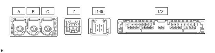
0.417,0.25 0.833,0.5
0.417,0.25
0.896,0.25 1.313,0.5
0.417,0.25
1.385,0.25 1.802,0.5
0.417,0.25
2.25,0.25 2.667,0.5
0.417,0.25
3.083,0.25 3.5,0.5
0.417,0.25
5.167,0.25 5.583,0.5
0.417,0.25
0.583,0.313 0.74,0.51
0.156,0.198
10
false
A
1.063,0.313 1.219,0.51
0.156,0.198
10
false
B
1.542,0.313 1.698,0.51
0.156,0.198
10
false
C
2.417,0.302 2.76,0.542
0.344,0.24
10
false
t1
3.177,0.302 3.521,0.542
0.344,0.24
10
false
I149
5.26,0.302 5.604,0.542
0.344,0.24
10
false
I72
| Terminal No. (Symbol) | Terminal Description | Condition | Specified Condition |
|---|---|---|---|
| I72-1 (+B) - I72-20 (E) | Power source (+B) | Always | 11 to 14 V |
| I72-3 (SIG-) - I72-20 (E) | Ground | Always | Below 1 V |
| I72-4 (IND1) - I72-20 (E) | Emergency call switch red indicator illumination signal | For 5 seconds after turning the power switch on (IG) | 1 to 8.5 V |
| Power switch off | Below 1 V | ||
| I72-5 (MCVD) - I72-20 (E) | Telephone microphone assembly power supply | Power switch on (IG) | 7.5 to 8.5 V |
| Power switch off | Below 1 V | ||
| I72-6 (MCI+) - I72-20 (E) | Microphone voice signal | Voice being input to telephone microphone assembly | A waveform synchronized with microphone voice signal is input |
| I72-7 (MCI-) - I72-20 (E) | Microphone voice signal | Always | Below 1 V |
| I72-13 (GSW) - I72-20 (E) | Collision detection signal | Power switch on (IG) | Pulse generation (Refer to waveform 1) |
| I72-14 (MUTE) - I72-20 (E) | MUTE Signal | Audio system playing | Above 3.5 V |
| Emergency call mode | Below 1 V | ||
| I72-15 (USBV) - I72-20 (E) | Telephone microphone assembly power supply | Power switch on (IG) | 4.75 to 5.25 V |
| Power switch off | Below 1 V | ||
| I72-16 (MCO+) - I72-20 (E) | Microphone voice signal | Voice being input to telephone microphone assembly | A waveform synchronized with microphone voice signal is input |
| I72-17 (VOT+) - I72-20 (E)* | Sent voice signal | Calling while using the operator service | A waveform synchronized with the received voice is output |
| I72-19 (IG2) - I72-20 (E) | Power source (IG) | Power switch on (IG) | 11 to 14 V |
| Power switch off | Below 1 V | ||
| I72-20 (E) - Body ground | Ground | Always | Below 1 V |
| I72-21 (SIG1) - I72-3 (SIG-) | Emergency call switch button condition signal | Emergency call switch not pressed | 1.3 to 1.9 V |
| Emergency call switch pressed | 0.5 to 0.8 V | ||
| I72-22 (IND2) - I72-20 (E) | Emergency call switch green indicator illumination signal | For 5 seconds after turning the power switch on (IG) | 1 to 8.5 V |
| Power switch off | Below 1 V | ||
| I72-23 (SGND) - I72-20 (E) | Shield ground | Always | Below 1 V |
| I72-25 (CANP) | CAN communication signal | - | - |
| I72-26 (CANN) | CAN communication signal | - | - |
| I72-31 (USBG) - Body ground | Shield ground | Always | Below 1 V |
| I72-32 (MCO-) - I72-20 (E) | Microphone voice signal | Always | Below 1 V |
| I72-33 (VOT-) - I72-20 (E)* | Sent voice signal | Calling while using the operator service | A waveform synchronized with the received voice is output |
| I149-1 (SPI+) - I72-20 (E) | Sound signal | Audio system playing | A waveform synchronized with sound signals is output |
| I149-2 (SPI-) - I72-20 (E) | Sound signal | Audio system playing | A waveform synchronized with sound signals is output |
| I149-3 (SPO+) - I72-20 (E) | Sound signal | Emergency call mode | A waveform synchronized with the received voice is output |
| I149-4 (SPO-) - I72-20 (E) | Sound signal | Emergency call mode | A waveform synchronized with the received voice is output |
| t1-1 (USB-) | USB communication line | - | - |
| t1-2 (USB+) | USB communication line | - | - |
| t1-3 (USBS) - Body ground | Shield ground | Always | Below 1 V |
*: for Navigation Receiver Type
NAVIGATION RECEIVER ASSEMBLY (w/ Navigation System)
RADIO AND DISPLAY RECEIVER ASSEMBLY (w/o Navigation System)