8ZR-FXE ENGINE MECHANICAL ENGINE UNIT REASSEMBLY
PROCEDURE

 11420
1.INSTALL STIFFENING CRANKCASE ASSEMBLY
11420
1.INSTALL STIFFENING CRANKCASE ASSEMBLY
- NOTICE:
-
It is not necessary to remove ring pins unless they are being replaced.
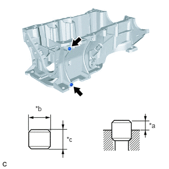
| *a | Protrusion Height |
| *b | 11 mm |
| *c | 8.0 mm |
Using a plastic hammer, tap 2 new ring pins into the stiffening crankcase assembly.
- Standard Ring Pin:
Item Protrusion Height Height Width Ring pin 4.0 mm (0.157 in.) 8.0 mm (0.315 in.) 11 mm (0.433 in.)
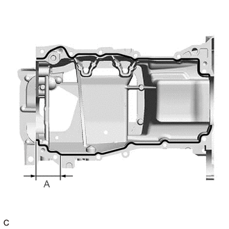
Apply seal packing as shown in the illustration.
- Seal Packing:
Toyota Genuine Seal Packing Black, Three Bond 1207B or equivalent
- Standard Seal Packing Diameter:
Area Specified Condition Continuous Line 2.0 to 3.0 mm (0.0787 to 0.118 in.) (A) 4.5 to 5.5 mm (0.177 to 0.217 in.)
- Application Length (A):
56 mm (2.20 in.)
- NOTICE:
- ·
Remove any oil from the contact surfaces.
·Install the stiffening crankcase assembly within 3 minutes and tighten the bolts within 15 minutes of applying seal packing.
·Do not start the engine for at least 2 hours after installing the stiffening crankcase assembly.
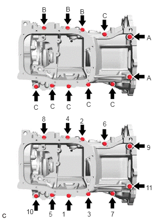
Install the stiffening crankcase assembly with the 11 bolts in the order shown in the illustration.
- Torque:
- 21 N*m (214 kgf*cm, 15 ft.*lbf)
- Bolt Length:
Item Specified Condition Bolt (A) 138 mm (5.43 in.) Bolt (B) 35 mm (1.38 in.) Bolt (C) 70 mm (2.76 in.)
Recheck the torque for the bolts (1) and (2).
- Torque:
- 21 N*m (214 kgf*cm, 15 ft.*lbf)
Wipe off any excess seal packing with a clean piece of cloth.
15100
2.INSTALL OIL PUMP ASSEMBLY
- NOTICE:
-
It is not necessary to remove ring pins unless they are being replaced.
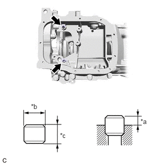
| *a | Protrusion Height |
| *b | 11 mm |
| *c | 8.0 mm |
Using a plastic hammer, tap 2 new ring pins into the stiffening crankcase assembly.
- Standard Ring Pin:
Item Protrusion Height Height Width Ring pin 3.0 mm (0.118 in.) 8.0 mm (0.315 in.) 11 mm (0.433 in.)
Install the oil pump assembly.
89491
3.INSTALL ENGINE OIL LEVEL SENSOR
12102A
4.INSTALL NO. 2 OIL PAN SUB-ASSEMBLY
- NOTICE:
-
If a stud bolt is deformed or its threads are damaged, replace it.
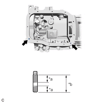
| *a | 9 mm (0.354 in.) |
| *b | 19 mm (0.748 in.) |
Using an E6 "TORX" socket wrench, install the 2 stud bolts as shown in the illustration.
- Torque:
- 5.0 N*m (51 kgf*cm, 44 in.*lbf)
Remove any remaining seal packing.
- NOTICE:
- ·
Remove any oil from the contact surfaces.
·Install the No. 2 oil pan sub-assembly within 3 minutes and tighten the bolts within 10 minutes of applying seal packing.
·Do not add engine oil for at least 2 hours after installing the No. 2 oil pan sub-assembly.
·Keep the contact surfaces of the stiffening crankcase assembly and No. 2 oil pan sub-assembly free of oil.
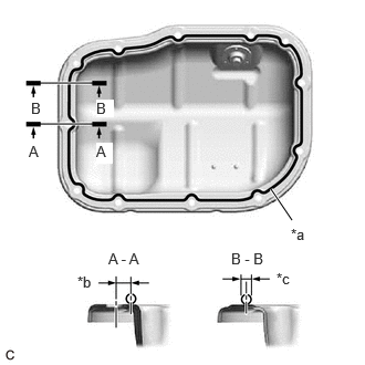
| *a | Seal Packing |
| *b | 6.0 mm |
| *c | 3.0 to 4.5 mm |
Apply seal packing in a continuous line as shown in the illustration.
- Seal Packing:
Toyota Genuine Seal Packing Black, Three Bond 1207B or equivalent
- Application Specification:
Area Seal Packing Diameter Distance from Center of Bolt Hole to Center of Seal Packing (A) - (A) 3.0 to 4.5 mm (0.118 to 0.177 in.) 6.0 mm (0.236 in.) (B) - (B) -
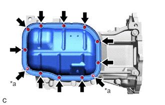
| *a | Nut |
Install the No. 2 oil pan sub-assembly to the stiffening crankcase assembly with the 10 bolts and 2 nuts.
- Torque:
- 10 N*m (102 kgf*cm, 7 ft.*lbf)
12101A
5.INSTALL OIL PAN DRAIN PLUG
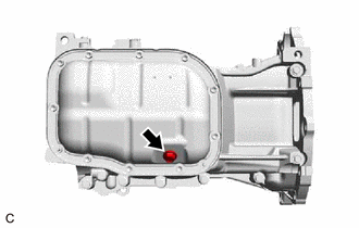
Install a new gasket and oil pan drain plug to the No. 2 oil pan sub-assembly.
- Torque:
- 37 N*m (377 kgf*cm, 27 ft.*lbf)
11401L
6.INSTALL REAR ENGINE OIL SEAL
12204
7.INSTALL PCV VALVE (VENTILATION VALVE SUB-ASSEMBLY)
11445A
8.INSTALL CYLINDER BLOCK WATER JACKET SPACER
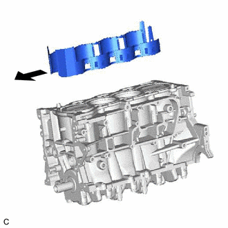

|
Front of Engine |
Install the 2 cylinder block water jacket spacers to the cylinder block sub-assembly as shown in the illustration.
- NOTICE:
-
Make sure that the water jacket spacer does not stick out from the top surface of the cylinder block sub-assembly.
11115
9.INSTALL CYLINDER HEAD GASKET
11101
10.INSTALL CYLINDER HEAD SUB-ASSEMBLY
- HINT:
-
The cylinder head set bolts are tightened in 3 progressive steps.
Clean the cylinder block sub-assembly and cylinder head sub-assembly with solvent.
Place the cylinder head sub-assembly on the cylinder block sub-assembly.
- NOTICE:
- ·
Remove any oil from the contact surface of the cylinder head sub-assembly.
·Place the cylinder head sub-assembly on the cylinder block sub-assembly gently in order not to damage the gasket with the bottom of the cylinder head sub-assembly.
Install the 10 cylinder head set plate washers to the 10 cylinder head set bolts.
Apply a light coat of engine oil to the threads and under the heads of the cylinder head set bolts.
Step 1:
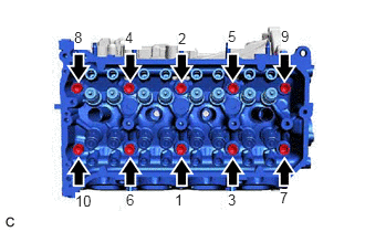
Using a 10 mm bi-hexagon socket wrench, install and uniformly tighten the 10 cylinder head set bolts in several steps in the order shown in the illustration.
- Torque:
- 49 N*m (500 kgf*cm, 36 ft.*lbf)
- NOTICE:
-
Do not drop the cylinder head set plate washers for the cylinder head set bolts into the cylinder head sub-assembly.
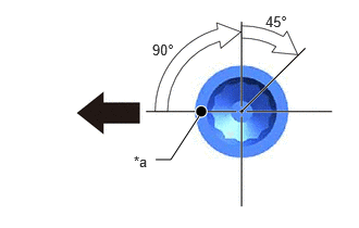
| *a | Paint Mark |
|
|
Front of Engine |
Step 2:
Mark each cylinder head set bolt head with paint as shown in the illustration.
Tighten the cylinder head set bolts 90° in the order shown in step 1.
Step 3:
Tighten the cylinder head set bolts another 45° in the order shown in step 1.
Check that the paint marks are now at a 135° angle.
- NOTICE:
-
Do not add engine oil for at least 2 hours after installing the cylinder head sub-assembly.
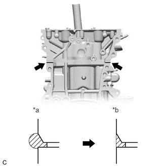
| *a | Before Wiping Off |
| *b | After Wiping Off |
After tightening the cylinder head set bolts, wipe off any seal packing that seeped out from the contact surfaces between the cylinder head sub-assembly and cylinder block sub-assembly.
- NOTICE:
- ·
Be sure to wipe off the seal packing from inside to outside, parallel to the joint line.
·Be sure to avoid clogging the bolt holes when wiping off the seal packing.
13716
11.INSTALL VALVE STEM CAP
Apply a light coat of engine oil to the valve stem ends.
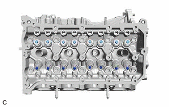
Install the 16 valve stem caps to the cylinder head sub-assembly.
- NOTICE:
- ·
Install each part to its original location.
·Do not drop the valve stem caps into the cylinder head sub-assembly.
13750
12.INSTALL VALVE LASH ADJUSTER ASSEMBLY
Inspect the 16 valve lash adjuster assemblies before installing them.
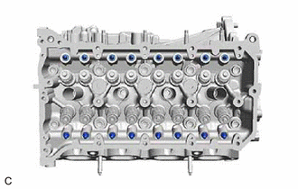
Install the 16 valve lash adjuster assemblies to the cylinder head sub-assembly.
- NOTICE:
-
Install each part to its original location.
13801
13.INSTALL NO. 1 VALVE ROCKER ARM SUB-ASSEMBLY
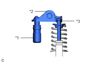
| *1 | Valve Lash Adjuster Assembly |
| *2 | No. 1 Valve Rocker Arm Sub-assembly |
| *3 | Valve Stem Cap |
Apply engine oil to the tips of the valve lash adjuster assemblies and valve stem caps.
Install the 16 No. 1 valve rocker arm sub-assemblies as shown in the illustration.
- NOTICE:
-
Install each part to its original location.
14.INSTALL RING PIN
- NOTICE:
-
It is not necessary to remove ring pins unless they are being replaced.
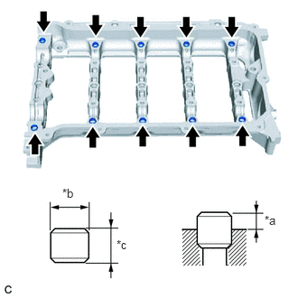
| *a | Protrusion Height |
| *b | 20 mm |
| *c | 13 mm |
Using a plastic hammer, tap 10 new ring pins into the camshaft housing sub-assembly.
- Standard Ring Pin:
Item Protrusion Height Height Width Ring pin 3.0 mm (0.118 in.) 13 mm (0.512 in.) 20 mm (0.787 in.)
15.INSTALL NO. 1 CAMSHAFT BEARING
Clean both surfaces of the No. 1 camshaft bearings.
Install the 2 No. 1 camshaft bearings.
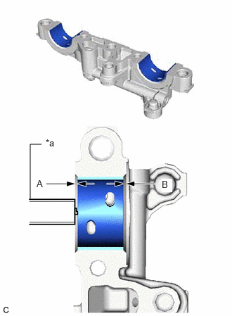
| *a | Vernier Caliper |
Using a vernier caliper, measure the distance between the No. 1 camshaft bearing cap edge and the No. 1 camshaft bearing edge.
- Standard Dimension (A) - (B):
0.7 mm (0.0276 in.) or less
- NOTICE:
-
Position the No. 1 camshaft bearings to the center of the camshaft bearing cap by measuring dimensions (A) and (B).
16.INSTALL NO. 2 CAMSHAFT BEARING
Clean both surfaces of the No. 2 camshaft bearings.
Install the 2 No. 2 camshaft bearings.
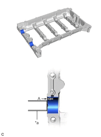
| *a | Vernier Caliper |
Using a vernier caliper, measure the distance between the camshaft housing sub-assembly edge and the No. 2 camshaft bearing edge.
- Dimension (A):
1.05 to 1.75 mm (0.0413 to 0.0689 in.)
- NOTICE:
-
Position the No. 2 camshaft bearings to the center of the camshaft housing sub-assembly by measuring dimension (A).
15678A
17.INSTALL OIL CONTROL VALVE FILTER
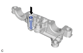
Check that no foreign matter is on the mesh of the oil control valve filter.
Install the oil control valve filter.
- NOTICE:
-
Do not touch the mesh when installing the oil control valve filter.
13512
18.INSTALL NO. 2 CAMSHAFT
13511
19.INSTALL CAMSHAFT
- HINT:
-
Perform Inspection After Repair after replacing the camshaft.
Clean the camshaft journals.
Apply a light coat of engine oil to the camshaft journals, camshaft housing sub-assembly and camshaft bearing caps.
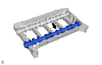
Install the camshaft to the camshaft housing sub-assembly.
20.INSTALL CAMSHAFT BEARING CAP
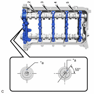
| *a | Knock Pin |
Confirm the marks and numbers on the camshaft bearing caps and place them in each proper position and direction.
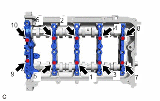
Tighten the 10 bearing cap bolts in the order shown in the illustration.
- Torque:
- 16 N*m (163 kgf*cm, 12 ft.*lbf)
13801
21.SET NO. 1 VALVE ROCKER ARM SUB-ASSEMBLY
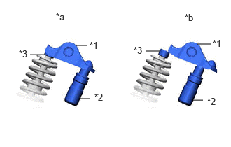
| *1 | No. 1 Valve Rocker Arm Sub-assembly |
| *2 | Valve Lash Adjuster Assembly |
| *3 | Valve Stem Cap |
| *a | Correct |
| *b | Incorrect |
Make sure that the No. 1 valve rocker arm sub-assemblies are installed as shown in the illustration.
11103
22.INSTALL CAMSHAFT HOUSING SUB-ASSEMBLY
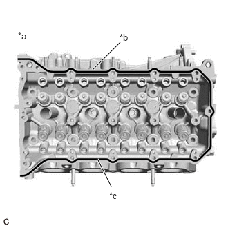
| *a | Cylinder Head Sub-assembly Upper Side |
| *b | Seal Packing |
| *c | 3.5 to 4.0 mm (0.138 to 0.157 in.) |
Apply seal packing in a continuous line as shown in the illustration.
- Seal Packing:
Toyota Genuine Seal Packing Black, Three Bond 1207B or equivalent
- NOTICE:
- ·
Remove any oil from the contact surfaces.
·Install the camshaft housing sub-assembly within 3 minutes and tighten the bolts within 10 minutes of applying seal packing.
·Do not start the engine for at least 2 hours after installation.
|
|
Bolt (A) |

|
Bolt (B) |
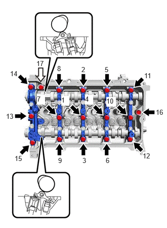
Set the camshaft and No. 2 camshaft as shown in the illustration.
Install the camshaft housing sub-assembly with the 17 bolts and tighten them in the order shown in the illustration.
- Torque:
- Bolt (A), (B) : 27 N*m (275 kgf*cm, 20 ft.*lbf)
- NOTICE:
- ·
After installing the camshaft housing sub-assembly, make sure that the cam lobes are positioned as shown in the illustration.
·If it is necessary to loosen any of the bolts during installation, remove the camshaft housing sub-assembly, clean the installation surfaces, and reapply seal packing.
·If it is necessary to remove the camshaft housing sub-assembly during installation, make sure that the previously applied seal packing does not enter any oil passages.
·After installing the camshaft housing sub-assembly, wipe off any seal packing that seeped out from between the camshaft housing sub-assembly and cylinder head sub-assembly.
13523G
23.INSTALL CAMSHAFT TIMING SPROCKET
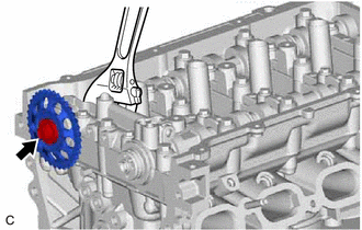
Using a wrench to hold the hexagonal portion of the No. 2 camshaft, tighten the bolt.
- Torque:
- 54 N*m (551 kgf*cm, 40 ft.*lbf)
13050
24.INSTALL CAMSHAFT TIMING GEAR ASSEMBLY
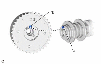
| *a | Knock Pin |
| *b | Knock Pin Hole |
Align and fit the knock pin of the camshaft to the knock pin hole of the camshaft timing gear assembly.
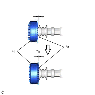
| *1 | Camshaft Timing Gear Assembly |
| *a | Camshaft Flange |
| *b | No Gap |
Check that there is no gap between the camshaft timing gear assembly and camshaft flange.
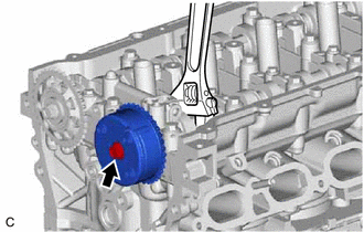
Using a wrench to hold the hexagonal portion of the camshaft, tighten the bolt.
- Torque:
- 54 N*m (551 kgf*cm, 40 ft.*lbf)
|
|
Lock |
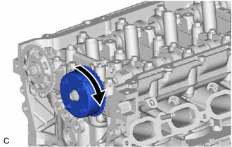
Check that the camshaft timing gear assembly can move in the retard direction (clockwise) and locks in the most retarded position.
13521A
25.INSTALL CRANKSHAFT TIMING GEAR KEY
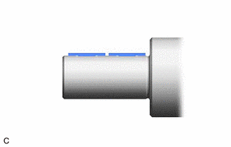
Using a plastic hammer, tap in the 2 crankshaft timing gear keys.
- HINT:
-
Tap in the crankshaft timing gear keys until they contact the crankshaft as shown in the illustration.
19315
26.INSTALL NO. 1 CRANKSHAFT POSITION SENSOR PLATE

Install the No. 1 crankshaft position sensor plate to the crankshaft with the "F" mark facing forward.
13507
27.INSTALL NO. 2 CHAIN SUB-ASSEMBLY
Temporarily install the crankshaft pulley set bolt to the crankshaft.
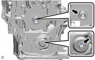
| *1 | Crankshaft Timing Gear Key |
Set the crankshaft timing gear keys as shown in the illustration.
Turn the oil pump drive shaft so that the flat face is facing upward.
Remove the crankshaft pulley set bolt from the crankshaft.
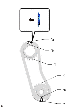
| *1 | Oil Pump Drive Gear |
| *2 | Oil Pump Drive Shaft Gear |
| *a | Mark Plate (Yellow) |
| *b | Timing Mark |
|
|
Front of Engine |
Align the mark plates (yellow) with the timing mark of the oil pump drive gear and oil pump drive shaft gear as shown in the illustration.
- HINT:
-
Make sure the mark plates (yellow) of the No. 2 chain sub-assembly are facing away from the engine assembly.
With the No. 2 chain sub-assembly placed around the oil pump drive gear and oil pump drive shaft gear, install the oil pump drive gear to the crankshaft and temporarily install the oil pump drive shaft gear to the oil pump drive shaft.
Temporarily install the oil pump drive shaft gear nut.
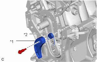
| *1 | Chain Tensioner Plate |
| *2 | Chain Damper Spring |
Install the chain damper spring to the chain tensioner plate, and then install the chain tensioner plate with the bolt.
- Torque:
- 10 N*m (102 kgf*cm, 7 ft.*lbf)
Temporarily install the crankshaft pulley to the crankshaft with the crankshaft pulley set bolt.
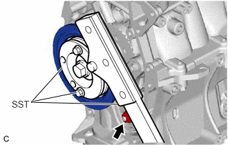
Using SST, hold the crankshaft pulley and tighten the oil pump drive shaft gear nut.
- SST
- 09213-58014 (91551-80840)
09330-00021
- Torque:
- 28 N*m (286 kgf*cm, 21 ft.*lbf)
Remove SST, the crankshaft pulley set bolt and crankshaft pulley.
13521
28.INSTALL CRANKSHAFT TIMING SPROCKET
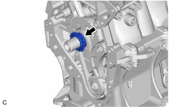
Install the crankshaft timing sprocket to the crankshaft.
29.SET NO. 1 CYLINDER TO TDC (COMPRESSION)
Temporarily install the crankshaft pulley set bolt to the crankshaft.
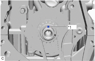
| *1 | Crankshaft Timing Gear Key |
Turn the crankshaft clockwise until the crankshaft timing gear key is facing upward.
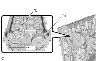
| *a | Timing Mark |
| *b | Timing Mark (Rectangle) |
| *c | Mark (Circle) |
Check that the timing marks on the camshaft timing gear assembly and camshaft timing sprocket are aligned as shown in the illustration.
- HINT:
-
There are 3 marks on the camshaft timing sprocket. Make sure that the timing mark (rectangle) is at the top.
Remove the crankshaft pulley set bolt from the crankshaft.
13506
30.INSTALL CHAIN SUB-ASSEMBLY
13562
31.INSTALL NO. 2 CHAIN VIBRATION DAMPER
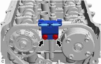
Install the No. 2 chain vibration damper to the camshaft housing sub-assembly with the 2 bolts.
- Torque:
- 10 N*m (102 kgf*cm, 7 ft.*lbf)
13559
32.INSTALL CHAIN TENSIONER SLIPPER
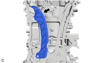
Install the chain tensioner slipper to the cylinder block sub-assembly.
15609D
33.INSTALL OIL FILTER BRACKET WITH HEAD STRAIGHT SCREW PLUG
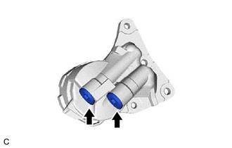
Using a 10 mm hexagon socket wrench, install 2 new gaskets and the 2 oil filter bracket with head straight screw plugs to the oil filter bracket.
- Torque:
- 44 N*m (449 kgf*cm, 32 ft.*lbf)
11302
34.INSTALL TIMING CHAIN COVER SUB-ASSEMBLY
- NOTICE:
-
If the stud bolts are deformed or the threads are damaged, replace them.
Type A:
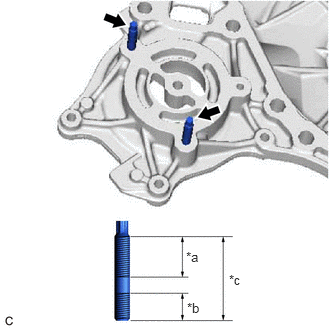
| *a | 21 mm (0.827 in.) |
| *b | 9 mm (0.354 in.) |
| *c | 34 mm (1.34 in.) |
Using an E6 "TORX" socket wrench, install the 2 stud bolts as shown in the illustration.
- Torque:
- 5.0 N*m (51 kgf*cm, 44 in.*lbf)
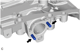
Install the 2 stud bolts as shown in the illustration.
- Torque:
- 5.0 N*m (51 kgf*cm, 44 in.*lbf)
Remove any remaining seal packing.
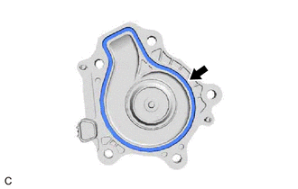
Install a new gasket to the engine water pump assembly.
- HINT:
-
Be sure to clean the contact surfaces.
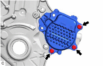
Install the engine water pump assembly to the timing chain cover sub-assembly with the 3 bolts.
- Torque:
- 21 N*m (214 kgf*cm, 15 ft.*lbf)
Clean the contact surfaces of the timing chain cover sub-assembly, camshaft housing sub-assembly, cylinder head sub-assembly, cylinder block sub-assembly and stiffening crankcase assembly, and confirm that no oil, moisture, or other foreign matter is on the surfaces.
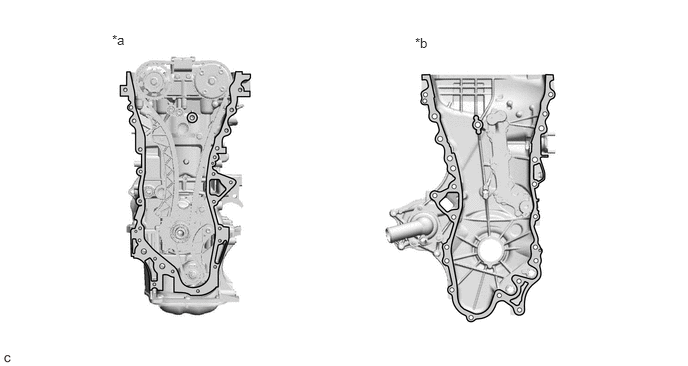
| *a | Cylinder Head Sub-assembly and Cylinder Block Sub-assembly Side | *b | Timing Chain Cover Sub-assembly Side |

|
Clean and degrease | - | - |
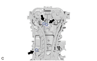
Install 3 new O-rings to the cylinder head sub-assembly and cylinder block sub-assembly.
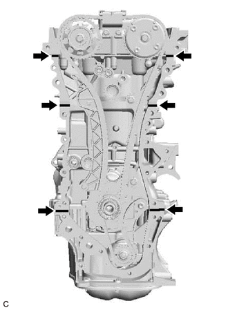
Apply seal packing to the engine unit as shown in the illustration.
- Seal Packing:
Toyota Genuine Seal Packing Black, Three Bond 1207B or equivalent
- Seal Packing Diameter:
5.0 mm (0.197 in.)
- NOTICE:
-
Install the timing chain cover sub-assembly within 3 minutes and tighten the bolts within 10 minutes of applying seal packing.
Apply seal packing to the timing chain cover sub-assembly in a continuous line as shown in the illustration.
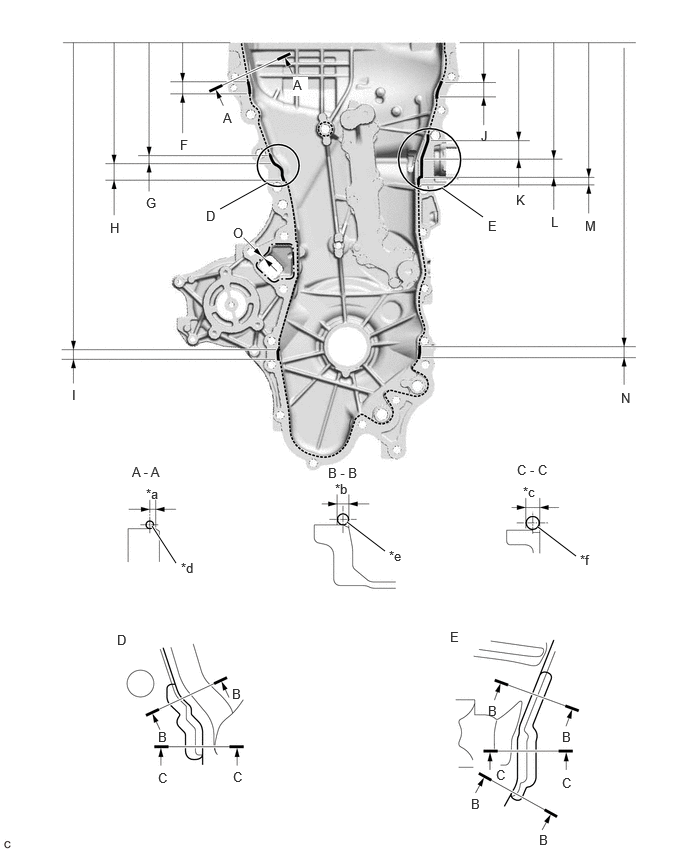
| *a | 2.5 mm | *b | 5.0 mm |
| *c | 7.5 mm | *d | 2.5 to 3.5 mm |
| *e | 4.5 to 5.5 mm | *f | 7.0 to 8.0 mm |
- Seal Packing:
Item Seal Packing Dashed line Toyota Genuine Seal Packing Black, Three Bond 1207B or equivalent Continuous line Alternate long and short dashed line Toyota Genuine Seal Packing 1282B, Three Bond 1282B or equivalent
- Application Specification:
Area Seal Packing Diameter Distance from Edge of Cover to: Seal Packing Application Length Distance from Top of Cover to Top of Seal Packing Dashed line 2.5 to 3.5 mm (0.0984 to 0.138 in.) Center of seal packing
2.5 mm (0.0984 in.)- - Continuous line 4.5 to 5.5 mm (0.177 to 0.217 in.) or 7.0 to 8.0 mm (0.276 to 0.315 in.) - - - Alternate long and short dashed line 4.0 mm (0.157 in.) Center of seal packing
3.0 mm (0.118 in.)- - (A) - (A) 2.5 to 3.5 mm (0.0984 to 0.138 in.) Center of seal packing
2.5 mm (0.0984 in.)- - (B) - (B) 4.5 to 5.5 mm (0.177 to 0.217 in.) Opposite edge of seal packing
5.0 mm (0.197 in.)- - (C) - (C) 7.0 to 8.0 mm (0.276 to 0.315 in.) Opposite edge of seal packing
7.5 mm (0.295 in.)- - (F) 4.5 to 5.5 mm (0.177 to 0.217 in.) - 15.5 mm (0.610 in.) 50.4 mm (1.98 in.) (G) 4.5 to 5.5 mm (0.177 to 0.217 in.) - 10.3 mm (0.406 in.) 143.1 mm (5.63 in.) (H) 7.0 to 8.0 mm (0.276 to 0.315 in.) - 19.5 mm (0.768 in.) 153.4 mm (6.04 in.) (I) 4.5 to 5.5 mm (0.177 to 0.217 in.) - 16.0 mm (0.630 in.) 385.8 mm (1.27 ft.) (J) 4.5 to 5.5 mm (0.177 to 0.217 in.) - 18.6 mm (0.732 in.) 51.4 mm (2.02 in.) (K) 4.5 to 5.5 mm (0.177 to 0.217 in.) - 25.3 mm (0.996 in.) 121.9 mm (4.80 in.) (L) 7.0 to 8.0 mm (0.276 to 0.315 in.) - 25.8 mm (1.02 in.) 147.2 mm (5.80 in.) (M) 4.5 to 5.5 mm (0.177 to 0.217 in.) - 5.1 mm (0.201 in.) 173.0 mm (6.81 in.) (N) 4.5 to 5.5 mm (0.177 to 0.217 in.) - 14.6 mm (0.575 in.) 385.8 mm (1.27 ft.) (O) 4.0 mm (0.157 in.) Center of seal packing
3.0 mm (0.118 in.)- -
- NOTICE:
-
Install the timing chain cover sub-assembly within 3 minutes and tighten the bolts within 10 minutes of applying seal packing.
Clean the bolts and their installation holes.
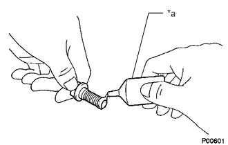
| *a | Adhesive |
Apply adhesive to 5 and a half threads or more of the end of the 2 bolts (E).
- Adhesive:
Toyota Genuine Adhesive 1324, Three Bond 1324 or equivalent
| *1 | Seal Washer |
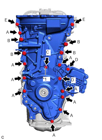
Temporarily install the timing chain cover sub-assembly with the 18 bolts and a new seal washer.
- Bolt Length:
Item Length Bolt (A), (E) 35 mm (1.38 in.) Bolt (B), (D) 55 mm (2.17 in.) Bolt (C) 40 mm (1.57 in.)
- NOTICE:
-
Make sure that there is no oil on the threads of the bolts.
Temporarily install the engine mounting bracket RH to the timing chain cover sub-assembly with the 3 bolts.
- Bolt Length:
Item Length Bolt 80 mm (3.15 in.)
- NOTICE:
-
Make sure that there is no oil on the threads of the bolts.
Install 2 new oil filter bracket O-rings to the timing chain cover sub-assembly.
Temporarily install the oil filter bracket to the timing chain cover sub-assembly with the 4 bolts.
- Bolt Length:
Item Length Bolt 35 mm (1.38 in.)
- NOTICE:
-
Make sure that there is no oil on the threads of the bolts.
Fully tighten the 25 bolts in the order shown in the illustration.
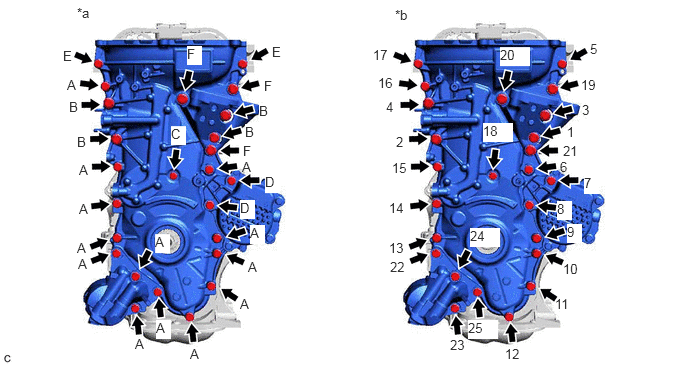
| *a | Torque | *b | Bolt Tightening Order |
- Torque:
- Bolt (A), (D), (E) : 25.5 N*m (260 kgf*cm, 19 ft.*lbf)
- Bolt (B), (F) : 51 N*m (520 kgf*cm, 38 ft.*lbf)
- Bolt (C) : 10 N*m (102 kgf*cm, 7 ft.*lbf)
- NOTICE:
- ·
Tighten the bolts within 10 minutes of applying seal packing.
·Do not add engine oil for at least 2 hours after installation.
·Do not start the engine for at least 2 hours after installation.
11302A
35.INSTALL TIMING CHAIN COVER OIL SEAL
16031
36.INSTALL WATER INLET WITH THERMOSTAT SUB-ASSEMBLY
83530
37.INSTALL ENGINE OIL PRESSURE SWITCH ASSEMBLY
89615
38.INSTALL KNOCK CONTROL SENSOR
11432A
39.INSTALL NO. 1 TAPER SCREW PLUG
Apply adhesive to 2 or 3 threads of the No. 1 taper screw plug, and install the No. 1 taper screw plug.
- Torque:
- 43 N*m (438 kgf*cm, 32 ft.*lbf)
- Adhesive:
Toyota Genuine Adhesive 1324, Three Bond 1324 or equivalent
- NOTICE:
- ·
Install the No. 1 taper screw plug within 3 minutes of applying adhesive.
·Do not start the engine for at least 1 hour after installing the No. 1 taper screw plug.
11401G
40.INSTALL CRANKSHAFT POSITION SENSOR
13471
41.INSTALL CRANKSHAFT PULLEY
13540
42.INSTALL NO. 1 CHAIN TENSIONER ASSEMBLY
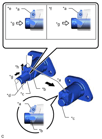
| *a | Cam |
| *b | Hook |
| *c | Plunger |
| *d | Pin |
| *e | Correct |
| *f | Incorrect |
| *g | Push |
| *h | Raise |
Raise the cam, then fully push in the plunger and engage the hook with the pin so that the plunger is in the position shown in the illustration.
- NOTICE:
-
Make sure that the cam engages with the first tooth of the plunger to allow the hook to pass over the pin.
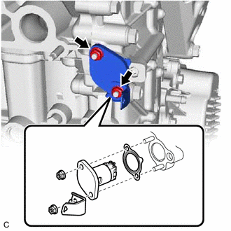
Install a new gasket, the bracket and No. 1 chain tensioner assembly to the timing chain cover sub-assembly with the 2 nuts.
- Torque:
- 12 N*m (122 kgf*cm, 9 ft.*lbf)
- NOTICE:
-
If the hook releases the plunger while the No. 1 chain tensioner assembly is being installed, set the hook again.
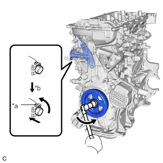
| *a | Hook |
| *b | Release |
Rotate the crankshaft counterclockwise slightly and check that the hook is released.

| *a | Plunger |
| *b | Plunger is extended |
Turn the crankshaft clockwise and check that the plunger is extended.
15600A
43.INSTALL OIL FILTER UNION
Using a 12 mm hexagon socket wrench, install the oil filter union to the oil filter bracket.
- Torque:
- 29.5 N*m (301 kgf*cm, 22 ft.*lbf)
15601
44.INSTALL OIL FILTER SUB-ASSEMBLY
11193
45.INSTALL SPARK PLUG TUBE GASKET
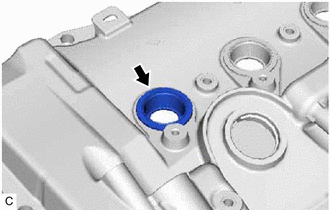
Install 4 new spark plug tube gaskets to the cylinder head cover sub-assembly.
11213
46.INSTALL CYLINDER HEAD COVER GASKET
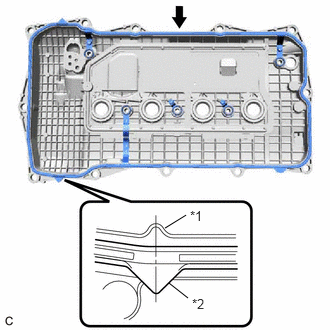
| *1 | Cylinder Head Cover Sub-assembly |
| *2 | Cylinder Head Cover Gasket |
Install 3 new cylinder head cover gaskets to the cylinder head cover sub-assembly.
- NOTICE:
- ·
Remove any oil from the contact surfaces.
·Misalignment between the center of the cylinder head cover sub-assembly rib and the center of the cylinder head gasket tab should be 4.0 mm (0.157 in.) or less.
11201
47.INSTALL CYLINDER HEAD COVER SUB-ASSEMBLY
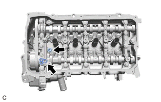
Install 2 new gaskets as shown in the illustration.
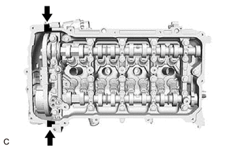
Apply seal packing as shown in the illustration.
- Seal Packing:
Toyota Genuine Seal Packing Black, Three Bond 1207B or equivalent
- Standard Diameter:
4.0 mm (0.157 in.)
- NOTICE:
- ·
Remove any oil from the contact surfaces.
·Install the cylinder head cover sub-assembly within 3 minutes and tighten the bolts within 15 minutes of applying seal packing.
·Do not start the engine for at least 2 hours after installation.
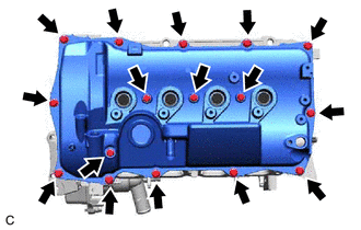
Install the cylinder head cover sub-assembly with the 16 bolts.
- Torque:
- 10 N*m (102 kgf*cm, 7 ft.*lbf)
- NOTICE:
-
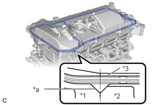 2.24,1.573 2.5,1.417 true 0.917,1.854 1.979,1.854 true 1.667,1.906 1.979,2.063 0.313,0.156 10 false *1 2.375,1.917 2.688,2.073 0.313,0.156 10 false *2 2.552,1.344 2.865,1.5 0.313,0.156 10 false *3 0.688,1.781 1,1.938 0.313,0.156 10 false *a
*1 Timing Chain Cover Sub-assembly *2 Camshaft Housing Sub-assembly *3 Cylinder Head Cover Gasket *a Projection
-
Misalignment between the contact surfaces of the timing chain cover sub-assembly and camshaft housing sub-assembly and the center of the cylinder head cover gasket tab should be 4.0 mm (0.157 in.) or less.
11101J
48.INSTALL CAMSHAFT TIMING OIL CONTROL VALVE ASSEMBLY
11101E
49.INSTALL CAMSHAFT POSITION SENSOR
19100P
50.INSTALL SPARK PLUG
12108A
51.INSTALL OIL FILLER CAP GASKET
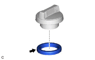
Install the oil filler cap gasket to the oil filler cap sub-assembly.
12108
52.INSTALL OIL FILLER CAP SUB-ASSEMBLY
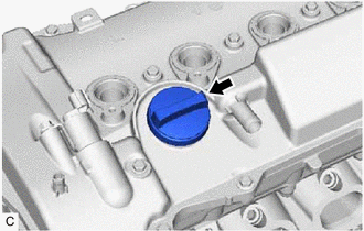
Install the oil filler cap sub-assembly to the cylinder head cover sub-assembly.