RM3660EC _58 Vehicle Interior _080733 HEATING / AIR CONDITIONING _0598792 AIR CONDITIONING SYSTEM(for HV Model (8ZR-FXE)) J

HEATING / AIR CONDITIONING  AIR CONDITIONING SYSTEM(for HV Model (8ZR-FXE))  Blower Motor Circuit  


DESCRIPTION

The blower motor with fan sub-assembly is operated by signals from the air conditioning amplifier assembly.

If the airflow volume is low or the blower speed cannot be changed, the following factors may be the cause.

Symptom Factor
Airflow volume cannot be changed
·

Air conditioning amplifier assembly malfunction

·

Blower motor with fan sub-assembly malfunction

·

Blower motor control malfunction

·

Harness or connector


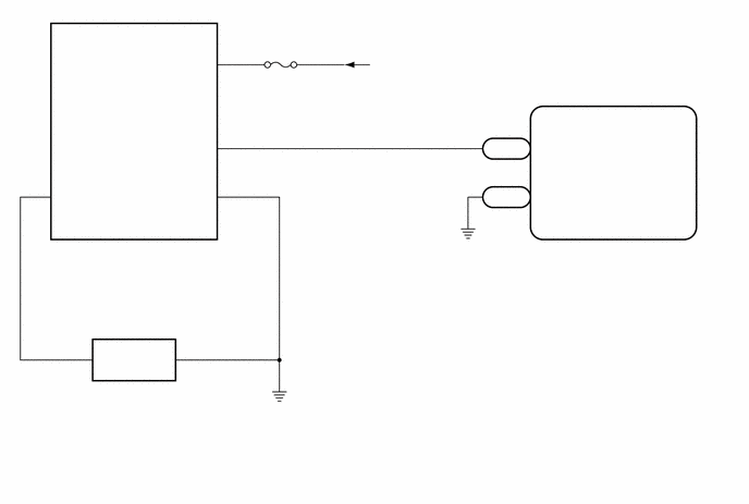
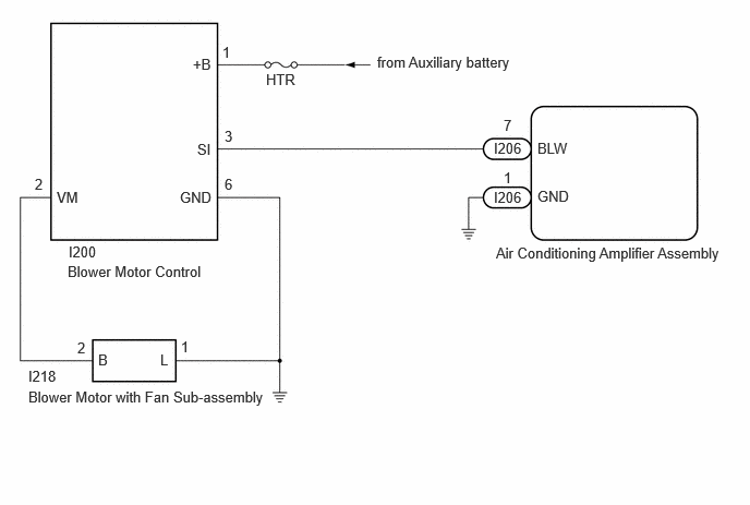
WIRING DIAGRAM

for TFTM Made:
E512294
0.271,3.708 2.677,3.969 2.406,0.26 10 false Blower Motor with Fan Sub-assembly 0.646,2.51 2.135,2.74 1.49,0.229 10 false Blower Motor Control 4.74,2.333 7.031,2.615 2.292,0.281 10 false Air Conditioning Amplifier Assembly 4.719,1.333 5.333,1.531 0.615,0.198 10 false I206 4.719,1.802 5.333,2 0.615,0.198 10 false I206 4.813,1.615 4.969,1.813 0.156,0.198 10 false 1 4.813,1.115 4.969,1.313 0.156,0.198 10 false 7 5.135,1.333 5.75,1.531 0.615,0.198 10 false BLW 5.135,1.792 5.75,1.99 0.615,0.198 10 false GND 2.542,0.677 3,0.875 0.458,0.198 10 false HTR 3.604,0.51 5.073,0.74 1.469,0.229 10 false from Auxiliary battery 0.271,3.51 0.885,3.708 0.615,0.198 10 false I199 0.656,2.323 1.271,2.521 0.615,0.198 10 false I200 0.938,3.354 1.094,3.552 0.156,0.198 10 false B 1.531,3.354 1.688,3.552 0.156,0.198 10 false L 0.542,1.802 0.927,2.01 0.385,0.208 10 false VM 1.719,1.802 2.104,2.01 0.385,0.208 10 false GND 1.885,1.344 2.271,1.552 0.385,0.208 10 false SI 1.844,0.531 2.229,0.74 0.385,0.208 10 false +B 2.125,0.417 2.281,0.615 0.156,0.198 10 false 1 2.146,1.219 2.302,1.417 0.156,0.198 10 false 3 2.146,1.677 2.302,1.875 0.156,0.198 10 false 6 1.729,3.229 1.885,3.427 0.156,0.198 10 false 1 0.74,3.24 0.896,3.438 0.156,0.198 10 false 2 0.333,1.677 0.49,1.875 0.156,0.198 10 false 2

for GTMC Made:
E512294E02
0.271,3.708 2.677,3.969 2.406,0.26 10 false Blower Motor with Fan Sub-assembly 0.646,2.51 2.135,2.74 1.49,0.229 10 false Blower Motor Control 4.74,2.333 7.031,2.615 2.292,0.281 10 false Air Conditioning Amplifier Assembly 4.719,1.333 5.333,1.531 0.615,0.198 10 false I206 4.719,1.802 5.333,2 0.615,0.198 10 false I206 4.813,1.615 4.969,1.813 0.156,0.198 10 false 1 4.813,1.115 4.969,1.313 0.156,0.198 10 false 7 5.135,1.333 5.75,1.531 0.615,0.198 10 false BLW 5.135,1.792 5.75,1.99 0.615,0.198 10 false GND 2.542,0.677 3,0.875 0.458,0.198 10 false HTR 3.604,0.51 5.073,0.74 1.469,0.229 10 false from Auxiliary battery 0.271,3.51 0.885,3.708 0.615,0.198 10 false I218 0.656,2.323 1.271,2.521 0.615,0.198 10 false I200 0.938,3.354 1.094,3.552 0.156,0.198 10 false B 1.531,3.354 1.688,3.552 0.156,0.198 10 false L 0.542,1.802 0.927,2.01 0.385,0.208 10 false VM 1.719,1.802 2.104,2.01 0.385,0.208 10 false GND 1.885,1.344 2.271,1.552 0.385,0.208 10 false SI 1.844,0.531 2.229,0.74 0.385,0.208 10 false +B 2.125,0.417 2.281,0.615 0.156,0.198 10 false 1 2.146,1.219 2.302,1.417 0.156,0.198 10 false 3 2.146,1.677 2.302,1.875 0.156,0.198 10 false 6 1.729,3.229 1.885,3.427 0.156,0.198 10 false 1 0.74,3.24 0.896,3.438 0.156,0.198 10 false 2 0.333,1.677 0.49,1.875 0.156,0.198 10 false 2

CAUTION / NOTICE / HINT

NOTICE:

Inspect the fuses for circuits related to this system before performing the following procedure.


PROCEDURE

1.PERFORM ACTIVE TEST USING GTS
a.

Perform the Active Test according to the display on the GTS.

Body Electrical > Air Conditioner > Active Test
Tester Display Measurement Item Control Range Diagnostic Note
Blower Level This test activates the Blower Motor to adjust the air volume High/Low.
(Blower motor with fan sub-assembly)
0: Air Volume Low
31: Air Volume High
Operate with ignition switch ON.
Body Electrical > Air Conditioner > Active Test
Tester Display
Blower Level
50004 450 1

Result:
Result Proceed to
Blower motor with fan sub-assembly does not operate A
Blower motor with fan sub-assembly operates but does not change speed B


A

2.CHECK HARNESS AND CONNECTOR (AUXILIARY BATTERY AND BODY GROUND - BLOWER MOTOR CONTROL)

B

14.CONFIRM MODEL
2.CHECK HARNESS AND CONNECTOR (AUXILIARY BATTERY AND BODY GROUND - BLOWER MOTOR CONTROL)
a.
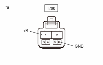
E514997C01
1.49,0.156 1.927,0.396 0.438,0.24 1,1.052 1.427,1.177 true 2.01,1.417 2.438,1.542 true 0.177,0.156 0.49,0.313 0.313,0.156 10 false *a 1.583,0.198 2.198,0.396 0.615,0.198 10 false I200 2.49,1.469 2.948,1.667 0.458,0.198 10 false GND 0.771,0.948 1.229,1.146 0.458,0.198 10 false +B
*a Front view of wire harness connector
(to Blower Motor Control)


Disconnect the I200 blower motor control connector.


b.

Measure the resistance according to the value(s) in the table below.

Standard Resistance:
Tester Connection Condition Specified Condition
I200-6 (GND) - Body ground Always Below 1 Ω


c.

Measure the voltage according to the value(s) in the table below.

Standard Voltage:
Tester Connection Condition Specified Condition
I200-1 (+B) - Body ground Ignition switch off 11 to 14 V


Result:
Proceed to
OK
NG


OK

3.CHECK HARNESS AND CONNECTOR (BLOWER MOTOR CONTROL - AIR CONDITIONING AMPLIFIER ASSEMBLY)

NG

REPAIR OR REPLACE HARNESS OR CONNECTOR

3.CHECK HARNESS AND CONNECTOR (BLOWER MOTOR CONTROL - AIR CONDITIONING AMPLIFIER ASSEMBLY)
a.

Disconnect the I206 air conditioning amplifier assembly connector.


b.

Disconnect the I200 blower motor control connector.


c.

Measure the resistance according to the value(s) in the table below.

Standard Resistance:
Tester Connection Condition Specified Condition
I206-7 (BLW) - I200-3 (SI) Always Below 1 Ω
I206-7 (BLW) or I200-3 (SI) - Other terminals and body ground Always 10 kΩ or higher


Result:
Proceed to
OK
NG


OK

4.INSPECT BLOWER MOTOR WITH FAN SUB-ASSEMBLY

NG

REPAIR OR REPLACE HARNESS OR CONNECTOR

5.CONFIRM MODEL
Result:
Result Proceed to
for TFTM Made A
for GTMC Made B


A

6.CHECK HARNESS AND CONNECTOR (BLOWER MOTOR CONTROL - BLOWER MOTOR WITH FAN SUB-ASSEMBLY)

B

10.CHECK HARNESS AND CONNECTOR (BLOWER MOTOR CONTROL - BLOWER MOTOR WITH FAN SUB-ASSEMBLY)
6.CHECK HARNESS AND CONNECTOR (BLOWER MOTOR CONTROL - BLOWER MOTOR WITH FAN SUB-ASSEMBLY)
a.

Disconnect the I200 blower motor control connector.


b.

Disconnect the I199 blower motor with fan sub-assembly connector.


c.

Measure the resistance according to the value(s) in the table below.

Standard Resistance:
Tester Connection Condition Specified Condition
I200-2 (VM) - I199-2 (B) Always Below 1 Ω
I200-2 (VM) - I199-2 (B) - Other terminals and body ground Always 10 kΩ or higher


Result:
Proceed to
OK
NG


OK

7.CHECK HARNESS AND CONNECTOR (BLOWER MOTOR WITH FAN SUB-ASSEMBLY - BODY GROUND)

NG

REPAIR OR REPLACE HARNESS OR CONNECTOR

7.CHECK HARNESS AND CONNECTOR (BLOWER MOTOR WITH FAN SUB-ASSEMBLY - BODY GROUND)
a.
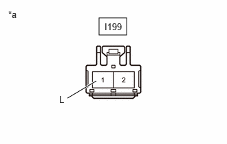
E514996C01
1.5,0.271 1.917,0.531 0.417,0.26 1.021,1.49 1.458,1.229 true 0.125,0.135 0.438,0.292 0.313,0.156 10 false *a 0.896,1.427 1.052,1.625 0.156,0.198 10 false L 1.583,0.323 2.198,0.521 0.615,0.198 10 false I199
*a Front view of wire harness connector
(to Blower Motor with Fan Sub-assembly)


Disconnect the I199 blower motor with fan sub-assembly connector.


b.

Measure the resistance according to the value(s) in the table below.

Standard Resistance:
Tester Connection Condition Specified Condition
I199-1 (L) - Body ground Always Below 1 Ω


Result:
Proceed to
OK
NG


OK

8.CHECK AIR CONDITIONING AMPLIFIER ASSEMBLY

NG

REPAIR OR REPLACE HARNESS OR CONNECTOR

8.CHECK AIR CONDITIONING AMPLIFIER ASSEMBLY
a.

Connect the I206 air conditioning amplifier assembly connector.


b.

Connect the I200 blower motor control connector.


c.

Connect the I199 blower motor with fan sub-assembly connector.


d.

Using an oscilloscope, check the waveform.
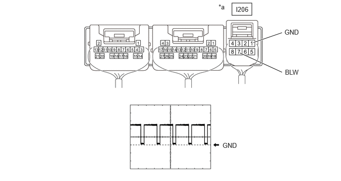
E445220C08
4.875,0.063 5.292,0.323 0.417,0.26 5.927,0.688 5.323,0.896 true 5.927,1.521 5.042,1.115 true 4.958,0.115 5.417,0.313 0.458,0.198 10 false I206 4.594,0.063 4.906,0.26 0.313,0.198 10 false *a 4.677,2.979 5.135,3.177 0.458,0.198 10 false GND 5.99,1.438 6.448,1.635 0.458,0.198 10 false BLW 5.979,0.594 6.438,0.792 0.458,0.198 10 false GND
*a Component with harness connected
(Air Conditioning Amplifier Assembly)
- -


Item Content
Terminal No. I206-7 (BLW) - I206-1 (GND)
Tool Setting 2 V/DIV., 1 ms./DIV.
Condition
·

Ignition switch ON

·

Blower speed: LO


HINT:

The waveform varies with the blower speed.


OK:

Waveform is similar to that shown in the illustration.


Result:
Proceed to
OK
NG


OK

9.CHECK BLOWER MOTOR CONTROL

NG

9.CHECK BLOWER MOTOR CONTROL
a.

Disconnect the I199 blower motor with fan sub-assembly connector.


b.

Measure the voltage according to the value(s) in the table below.

Standard Voltage:
Tester Connection Condition Specified Condition
I199-2 (B) - Body ground Ignition switch ON 0.5 to 13.5 V


OK:

The voltage changes with the blower speed.


Result:
Proceed to
OK
NG


OK

NG

10.CHECK HARNESS AND CONNECTOR (BLOWER MOTOR CONTROL - BLOWER MOTOR WITH FAN SUB-ASSEMBLY)
a.

Disconnect the I200 blower motor control connector.


b.

Disconnect the I218 blower motor with fan sub-assembly connector.


c.

Measure the resistance according to the value(s) in the table below.

Standard Resistance:
Tester Connection Condition Specified Condition
I200-2 (VM) - I218-2 (B) Always Below 1 Ω
I200-2 (VM) - I218-2 (B) - Other terminals and body ground Always 10 kΩ or higher


Result:
Proceed to
OK
NG


OK

11.CHECK HARNESS AND CONNECTOR (BLOWER MOTOR WITH FAN SUB-ASSEMBLY - BODY GROUND)

NG

REPAIR OR REPLACE HARNESS OR CONNECTOR

11.CHECK HARNESS AND CONNECTOR (BLOWER MOTOR WITH FAN SUB-ASSEMBLY - BODY GROUND)
a.
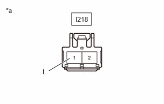
E514996C02
1.5,0.271 1.917,0.531 0.417,0.26 1.021,1.49 1.458,1.229 true 0.125,0.135 0.438,0.292 0.313,0.156 10 false *a 0.896,1.427 1.052,1.625 0.156,0.198 10 false L 1.583,0.323 2.198,0.521 0.615,0.198 10 false I218
*a Front view of wire harness connector
(to Blower Motor with Fan Sub-assembly)


Disconnect the I218 blower motor with fan sub-assembly connector.


b.

Measure the resistance according to the value(s) in the table below.

Standard Resistance:
Tester Connection Condition Specified Condition
I218-1 (L) - Body ground Always Below 1 Ω


Result:
Proceed to
OK
NG


OK

12.CHECK AIR CONDITIONING AMPLIFIER ASSEMBLY

NG

REPAIR OR REPLACE HARNESS OR CONNECTOR

12.CHECK AIR CONDITIONING AMPLIFIER ASSEMBLY
a.

Connect the I206 air conditioning amplifier assembly connector.


b.

Connect the I200 blower motor control connector.


c.

Connect the I218 blower motor with fan sub-assembly connector.


d.

Using an oscilloscope, check the waveform.

E445220C08
4.875,0.063 5.292,0.323 0.417,0.26 5.927,0.688 5.323,0.896 true 5.927,1.521 5.042,1.115 true 4.958,0.115 5.417,0.313 0.458,0.198 10 false I206 4.594,0.063 4.906,0.26 0.313,0.198 10 false *a 4.677,2.979 5.135,3.177 0.458,0.198 10 false GND 5.99,1.438 6.448,1.635 0.458,0.198 10 false BLW 5.979,0.594 6.438,0.792 0.458,0.198 10 false GND
*a Component with harness connected
(Air Conditioning Amplifier Assembly)
- -


Item Content
Terminal No. I206-7 (BLW) - I206-1 (GND)
Tool Setting 2 V/DIV., 1 ms./DIV.
Condition
·

Ignition switch ON

·

Blower speed: LO


HINT:

The waveform varies with the blower speed.


OK:

Waveform is similar to that shown in the illustration.


Result:
Proceed to
OK
NG


OK

13.CHECK BLOWER MOTOR CONTROL

NG

13.CHECK BLOWER MOTOR CONTROL
a.

Disconnect the I218 blower motor with fan sub-assembly connector.


b.

Measure the voltage according to the value(s) in the table below.

Standard Voltage:
Tester Connection Condition Specified Condition
I218-2 (B) - Body ground Ignition switch ON 0.5 to 13.5 V


OK:

The voltage changes with the blower speed.


Result:
Proceed to
OK
NG


OK

NG

14.CONFIRM MODEL
Result:
Result Proceed to
for TFTM Made A
for GTMC Made B


A

8.CHECK AIR CONDITIONING AMPLIFIER ASSEMBLY

B

12.CHECK AIR CONDITIONING AMPLIFIER ASSEMBLY