HEATING / AIR CONDITIONING AIR CONDITIONING SYSTEM(for HV Model (8ZR-FXE)) P05347A Refrigerant Gas Fluid Leak or Seal Failure
DESCRIPTION
This DTC is stored if the amount of refrigerant in the air conditioning system is insufficient.
The air conditioning amplifier assembly receives the ambient temperature signal, refrigerant pressure signal, etc. from various sensors.
Based on these signals, the air conditioning amplifier assembly detects the amount of refrigerant.
The A/C switch indicator is turned off and the air conditioning system is stopped if the amount of refrigerant is insufficient.
| DTC No. | Detection Item | DTC Detection Condition | Trouble Area | Memory |
|---|---|---|---|---|
| P05347A | Refrigerant Gas Fluid Leak or Seal Failure | Diagnosis Condition:
Normal operation refrigerant amount check conditions are met. The following condition is detected in the normal operation refrigerant shortage check Malfunction: Amount of refrigerant is judged to be insufficient by normal operation refrigerant amount check. Amount of refrigerant is insufficient Detection Time: Air conditioning system operating time: 15 minutes or more |
·
Refrigerant volume ·
Air conditioning pressure sensor ·
Harness or connector ·
Air conditioning amplifier assembly |
Memorized |
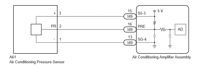
WIRING DIAGRAM
PROCEDURE
Install a manifold gauge set.
Prepare the vehicle according to the table below.
| Item | Condition |
|---|---|
| Doors | Fully open |
| A/C Switch | On |
| Recirculation/fresh Control Switch | Recirculation |
| Set Temperature | MAX COLD |
| Blower Speed | HI |
| Air Conditioning Air Inlet Temperature | 25 to 35°C (77 to 95°F) |
Compare the values displayed in the Data List and on the manifold gauge.
- Body Electrical > Air Conditioner > Data List
-
Tester Display Measurement Item Range Normal Condition Diagnostic Note Regulator Pressure Sensor Air conditioning pressure sensor -32.768 to 32.767 MPaG Actual refrigerant pressure displayed ·Refrigerant line (gas leak etc.)
·Air conditioning pressure sensor circuit malfunction
- Body Electrical > Air Conditioner > Data List
-
Tester Display Regulator Pressure Sensor - 50003 450 106
- Result:
Result Proceed to Data List value and manifold gauge set value do not match A Data List value matches manifold gauge set value B
A
B
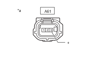
| *a | Front view of wire harness connector
(to Air Conditioner Pressure Sensor) |
Disconnect the A61 air conditioning pressure sensor connector.
Measure the voltage according to the value(s) in the table below.
- Standard Voltage:
Tester Connection Condition Specified Condition A61-3 (+) - Body ground Ignition switch ON 4.75 to 5.25 V
- Result:
Proceed to OK NG
OK
NG
Disconnect the A61 air conditioning pressure sensor connector.
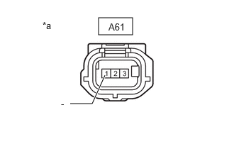
| *a | Front view of wire harness connector
(to Air Conditioner Pressure Sensor) |
Measure the resistance according to the value(s) in the table below.
- Standard Resistance:
Tester Connection Condition Specified Condition A61-1 (-) - Body ground Always Below 1 Ω
- Result:
Proceed to OK NG
OK
NG
Disconnect the A61 air conditioning pressure sensor connector.
Disconnect the I49 air conditioning amplifier assembly connector.
Measure the resistance according to the value(s) in the table below.
- Standard Resistance:
Tester Connection Condition Specified Condition A61-2 (PR) - I49-16 (PRE) Always Below 1 Ω A61-2 (PR) or I49-16 (PRE) - Other terminals and body ground Always 10 kΩ or higher
- Result:
Proceed to OK NG
OK
NG
- NOTICE:
- ·
If refrigerant pressure on the high pressure side becomes extremely high, the fail-safe function stops compressor operation.
·It is necessary to measure the voltage for a certain amount of time (approximately 10 minutes) because the malfunction may recur after a while.
- HINT:
-
When the outside air temperature is low (below -1.5°C (29.3°F)), the compressor stops due to operation of the ambient temp. sensor (thermistor assembly) and the evaporator temp. sensor (No. 1 cooler thermistor) to prevent the evaporator from freezing. In this case, perform the inspection in a warm indoor environment.
Connect the I49 air conditioning amplifier assembly connector.
Connect the A61 air conditioning pressure sensor connector.
Prepare the vehicle according to the table below.
| Item | Condition |
|---|---|
| Doors | Fully open |
| A/C Switch | On |
| Recirculation/fresh Control Switch | Recirculation |
| Set Temperature | MAX COLD |
| Blower Speed | HI |
| Air Conditioning Air Inlet Temperature | 25 to 35°C (77 to 95°F) |
Measure the voltage according to the value(s) in the table below.
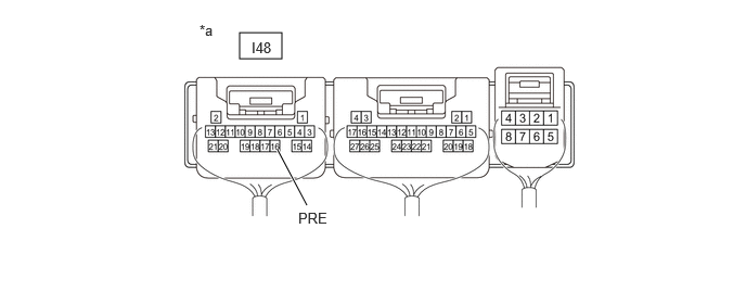
| *a | Component with harness connected
(Air Conditioning Amplifier Assembly) |
- | - |
- Standard Voltage:
Tester Connection Condition Specified Condition I49-16 (PRE) - Body ground A/C Switch ON (When compressor with motor assembly running) 0.74 to 4.61 V
Read the Data List according to the display on the GTS.
- Body Electrical > Air Conditioner > Data List
-
Tester Display Measurement Item Range Normal Condition Diagnostic Note Regulator Pressure Sensor Air conditioning pressure sensor -32.768 to 32.767 MPaG Actual refrigerant pressure displayed ·Refrigerant line (gas leak etc.)
·Air conditioning pressure sensor circuit malfunction
- Body Electrical > Air Conditioner > Data List
-
Tester Display Regulator Pressure Sensor - 50003 450 106
- OK:
The voltage and value displayed in the Data List change.
- Result:
Result Proceed to OK A NG (The voltage changes but the value displayed in the Data List does not change.) NG (The voltage does not change.) B
A
B
Disconnect the A61 air conditioning pressure sensor connector.
Disconnect the I49 air conditioning amplifier assembly connector.
Measure the resistance according to the value(s) in the table below.
- Standard Resistance:
Tester Connection Condition Specified Condition A61-1 (-) - I49-13 (SG-4) Always Below 1 Ω A61-1 (-) or I49-13 (SG-4) - Other terminals and body ground Always 10 kΩ or higher
- Result:
Proceed to OK NG
OK
NG
Disconnect the A61 air conditioning pressure sensor connector.
Disconnect the I49 air conditioning amplifier assembly connector.
Measure the resistance according to the value(s) in the table below.
- Standard Resistance:
Tester Connection Condition Specified Condition A61-3 (+) - I49-15 (S5-3) Always Below 1 Ω A61-3 (+) or I49-15 (S5-3) - Other terminals and body ground Always 10 kΩ or higher
- Result:
Proceed to OK NG
OK
NG