HEATING / AIR CONDITIONING AIR CONDITIONING SYSTEM(for HV Model (8ZR-FXE)) TERMINALS OF ECU
CHECK AIR CONDITIONING AMPLIFIER ASSEMBLY
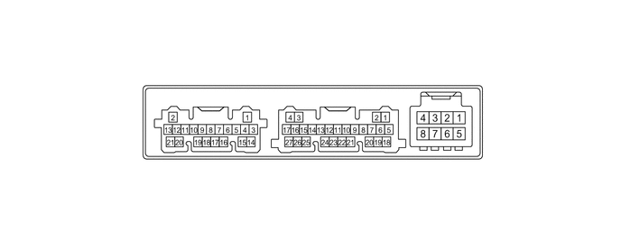
- HINT:
-
Make sure to wait at least 2 minutes after turning the ignition switch off before performing an ECU terminal inspection.
| Terminal No.
(Symbol) |
Terminal Description | Condition | Specified Condition |
|---|---|---|---|
|
*: w/ Ion generator sub-assembly |
|||
| I206-1 (GND) - Body ground | Ground for main power supply | Always | Below 1 Ω |
| I206-2 (NANO) - I206-1 (GND)* | Ion generator sub-assembly operation signal | ·
Ignition switch ON ·
Blower switch: ON → OFF |
Below 1 V → 4.75 to 5.25 V |
| I206-3 (B) - I206-1 (GND) | Power source (Back-up) | Ignition switch off | 11 to 14 V |
| I206-4 (IG+) - I206-1 (GND) | Power source (IG) | Ignition switch ON | 11 to 14 V |
| Ignition switch off | Below 1 V | ||
| I206-7 (BLW) - I206-1 (GND) | Blower motor speed control signal | ·
Ignition switch ON ·
Blower switch: LO |
Pulse generation
(See waveform "Blower") |
| Terminal No.
(Symbol) |
Terminal Description | Condition | Specified Condition |
|---|---|---|---|
|
*: w/ Ion generator sub-assembly |
|||
| I49-1 (CANL) - I49-2 (CANH) | CAN communication system | Ignition switch ON | Pulse generation |
| I49-3 (TAM) - I49-24 (SG-2) | Ambient temp. sensor (thermistor assembly) signal | ·
Ignition switch ON ·
Ambient temperature: 25°C (77°F) |
1.05 to 1.45 V |
·
Ignition switch ON ·
Ambient temperature: 40°C (104°F) |
0.64 to 0.87 V | ||
| I49-4 (TR) - I49-23 (SG-1) | Room temp. sensor (cooler thermistor) signal | ·
Ignition switch ON ·
Cabin temperature: 25°C (77°F) |
1.05 to 1.45 V |
·
Ignition switch ON ·
Cabin temperature: 40°C (104°F) |
0.64 to 0.87 V | ||
| I49-7 (LIN1) - I206-1 (GND) | LIN communication signal | Ignition switch ON | Pulse generation
(See waveform "Control panel LIN communication") |
| I49-13 (SG-4) - Body ground | Ground for air conditioning pressure sensor | Always | Below 1 Ω |
| I49-15 (S5-3) - I49-13 (SG-4) | Power supply for air conditioning pressure sensor | Ignition switch ON | 4.75 to 5.25 V |
| Ignition switch off | Below 1 V | ||
| I49-16 (PRE) - I49-13 (SG-4) | Air conditioning pressure sensor signal | ·
Ignition switch ON (READY) ·
Air conditioning system operating ·
Refrigerant pressure: Normal pressure |
0.74 to 4.61 V |
| I49-23 (SG-1) - Body ground | Ground for room temp. sensor (cooler thermistor) | Always | Below 1 Ω |
| I49-24 (SG-2) - Body ground | Ground for ambient temp. sensor (thermistor assembly) | Always | Below 1 Ω |
| I49-26 (NAIN) - I206-1 (GND)* | Ion generator sub-assembly operation condition signal | ·
Ignition switch ON ·
Blower switch: ON → OFF |
Below 2.2 V → 4.75 to 5.25 V |
| Terminal No.
(Symbol) |
Terminal Description | Condition | Specified Condition |
|---|---|---|---|
| z26-1 (MODE_pot) - z26-16 (SG-Pots/TE) | Front mode damper position potentiometer signal input | ·
Ignition switch ON ·
Mode switch: DEF |
0.4 to 0.6 V |
·
Ignition switch ON ·
Mode switch: FACE |
3.49 to 3.69 V | ||
| z26-2 (MOF) - I206-1 (GND) | Front mode servo motor drive output (FOOT) | ·
Ignition switch ON ·
Mode switch: DEF to FACE |
11 to 14 V
(Servo motor operating) |
| z26-3 (TE) - z26-16 (SG-Pots/TE) | Evaporator temp. sensor (No. 1 cooler thermistor) signal | ·
Ignition switch ON ·
Evaporator temperature: 0°C (32°F) |
1.7 to 2.1 V |
·
Ignition switch ON ·
Evaporator temperature: 15°C (59°F) |
0.9 to 1.3 V | ||
| z26-4 (R/F_pot) - z26-16 (SG-Pots/TE) | Recirculation/Fresh damper position potentiometer signal input | ·
Ignition switch ON ·
Recirculation/Fresh switch: Fresh |
2.93 to 3.13 V |
·
Ignition switch ON ·
Recirculation/Fresh switch: Recirculation |
4.4 to 4.6 V | ||
| z26-5 (A/MDr_pot) - z26-16 (SG-Pots/TE) | Air mix damper position potentiometer signal input | ·
Ignition switch ON ·
Set temperature switch: MAX COOL |
4.4 to 4.6 V |
·
Ignition switch ON ·
Set temperature switch: MAX HOT |
0.43 to 0.63 V | ||
| z26-6 (RrMODE_pot) - z26-16 (SG-Pots/TE) | Rear mode damper position potentiometer signal input | ·
Ignition switch ON ·
Mode switch: DEF |
4.4 to 4.6 V |
·
Ignition switch ON ·
Mode switch: FACE |
0.86 to 1.06 V | ||
| z26-11 (MOD) - I206-1 (GND) | Front mode servo motor drive output (DEF) | ·
Ignition switch ON ·
Mode switch: FACE to DEF |
11 to 14 V
(Servo motor operating) |
| z26-12 (AMC) - I206-1 (GND) | Air mix servo motor drive output (COOL) | ·
Ignition switch ON ·
Set temperature switch: MAX HOT to MAX COOL |
11 to 14 V
(Servo motor operating) |
| z26-13 (AMH) - I206-1 (GND) | Air mix servo motor drive output (HOT) | ·
Ignition switch ON ·
Set temperature switch: MAX COOL to MAX HOT |
11 to 14 V
(Servo motor operating) |
| z26-14 (S5-Pots) - z26-16 (SG-Pots/TE) | Servo motor potentiometer circuit power source | Ignition switch ON | 4.75 to 5.25 V |
| Ignition switch off | Below 1 V | ||
| z26-16 (SG-Pots/TE) - Body ground | ·
Servo motor potentiometer circuit ground ·
Ground for evaporator temp. sensor (No. 1 cooler thermistor) |
Always | Below 1 Ω |
| z26-18 (REC) - I206-1 (GND) | Recirculation/Fresh servo motor drive output (REC) | ·
Ignition switch ON ·
Recirculation/Fresh switch: Fresh to Recirculation |
11 to 14 V
(Servo motor operating) |
| z26-19 (FRS) - I206-1 (GND) | Recirculation/Fresh servo motor drive output (FRS) | ·
Ignition switch ON ·
Recirculation/Fresh switch: Recirculation to Fresh |
11 to 14 V
(Servo motor operating) |
| z26-20 (RRF) - I206-1 (GND) | Rear mode servo motor drive output (FOOT) | ·
Ignition switch ON ·
Mode switch: DEF to FACE |
11 to 14 V
(Servo motor operating) |
| z26-21 (RRD) - I206-1 (GND) | Rear mode servo motor drive output (DEF) | ·
Ignition switch ON ·
Mode switch: FACE to DEF |
11 to 14 V
(Servo motor operating) |
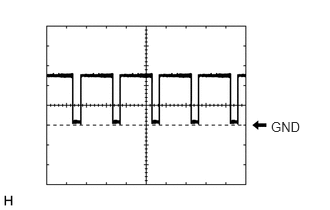
Waveform "Blower":
| Item | Content |
|---|---|
| Terminal No. | I206-7 (BLW) - I206-1 (GND) |
| Tool Setting | 2 V/DIV., 1 ms./DIV. |
| Condition | ·
Ignition switch ON ·
Blower switch: LO |
- HINT:
-
The waveform varies with the blower speed.
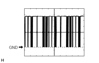
Waveform "Control panel LIN communication":
| Item | Content |
|---|---|
| Terminal No. | I49-7 (LIN1) - I206-1 (GND) |
| Tool Setting | 2 V/DIV., 20 ms./DIV. |
| Condition | Ignition switch ON |
CHECK AIR CONDITIONING CONTROL ASSEMBLY

| Terminal No.
(Symbol) |
Terminal Description | Condition | Specified Condition |
|---|---|---|---|
| I37-7 (LIN1) - Body ground | LIN communication signal | Ignition switch ON | Pulse generation
(See waveform) |
| I37-9 (IG+) - I37-13 (GND) | Power source (IG) | Ignition switch off | Below 1 V |
| Ignition switch ON | 11 to 14 V | ||
| I37-13 (GND) - Body ground | Ground for air conditioning control assembly | Always | Below 1 V |
Waveform:
| Item | Content |
|---|---|
| Terminal No. | I37-7 (LIN1) - Body ground |
| Tool Setting | 2 V/DIV., 20 ms./DIV. |
| Condition | Ignition switch ON |
HYBRID VEHICLE CONTROL ECU