POWER DISTRIBUTION MAIN BODY ECU INSTALLATION
CAUTION / NOTICE / HINT
- NOTICE:
- ·
Before replacing the main body ECU (multiplex network body ECU), refer to Service Bulletin.
·After the main body ECU (multiplex network body ECU) has been replaced, the automatic light control system will not operate until the engine is started.
PROCEDURE

 1.INSTALL MAIN BODY ECU (MULTIPLEX NETWORK BODY ECU) (for NR Series Engine)
- NOTICE:
- ·
Make sure that the connecting surfaces are free of foreign matter.
·Do not touch the main body ECU (multiplex network body ECU) connector.
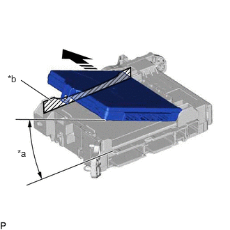
| *a | 20° or more |
| *b | Housing Sidewall |

|
Set in this Direction |
Set the main body ECU (multiplex network body ECU) to the position where the guide of the main body ECU (multiplex network body ECU) contacts the housing sidewall of the driver side junction block assembly as shown in the illustration.
- HINT:
-
Make sure to keep the angle at 20° or more as shown in the illustration.
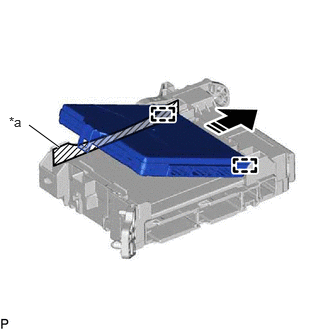
| *a | Housing Sidewall |
|
|
Slide in this Direction |
Slide the main body ECU (multiplex network body ECU) along the housing sidewall as shown in the illustration and engage the 2 guides.
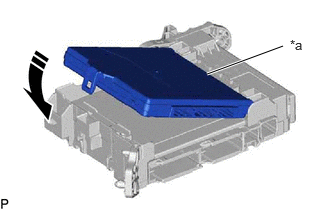
| *a | Side A |
|
|
Install in this Direction |
While keeping the main body ECU (multiplex network body ECU) in contact with side A of the driver side junction block assembly (axis of rotation), lower it as shown in the illustration.
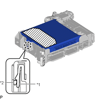
| *1 | Driver Side Junction Block Assembly |
| *2 | Main Body ECU (Multiplex Network Body ECU) |

|
Push Area |
Press the push area until the claw engages to install the main body ECU (multiplex network body ECU).
- NOTICE:
- ·
Make sure to press only the push area.
·Confirm the engagement of the main body ECU (multiplex network body ECU) and driver side junction block assembly by listening for the click sound of the lock engaging.
- HINT:
-
If a click sound cannot be heard, visually check the engagement of the lock. The engagement can also be confirmed if the main body ECU (multiplex network body ECU) and driver side junction block assembly are flush.
2.INSTALL MAIN BODY ECU (MULTIPLEX NETWORK BODY ECU) (except NR Series Engine)
- NOTICE:
- ·
Make sure that the connecting surfaces are free of foreign matter.
·Do not touch the main body ECU (multiplex network body ECU) connector.
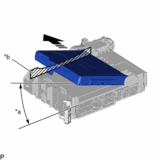
| *a | 20° or more |
| *b | Housing Sidewall |
|
|
Set in this Direction |
Set the main body ECU (multiplex network body ECU) to the position where the guide of the main body ECU (multiplex network body ECU) contacts the housing sidewall of the power distribution box assembly as shown in the illustration.
- HINT:
-
Make sure to keep the angle at 20° or more as shown in the illustration.
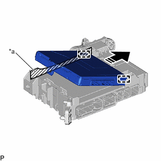
| *a | Housing Sidewall |
|
|
Slide in this Direction |
Slide the main body ECU (multiplex network body ECU) along the housing sidewall as shown in the illustration and engage the 2 guides.
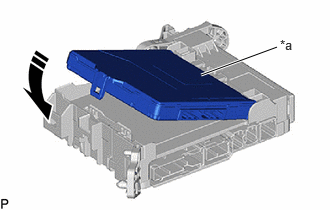
| *a | Side A |
|
|
Install in this Direction |
While keeping the main body ECU (multiplex network body ECU) in contact with side A of the power distribution box assembly (axis of rotation), lower it as shown in the illustration.
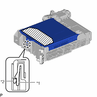
| *1 | Power Distribution Box Assembly |
| *2 | Main Body ECU (Multiplex Network Body ECU) |
|
|
Push Area |
Press the push area until the claw engages to install the main body ECU (multiplex network body ECU).
- NOTICE:
- ·
Make sure to press only the push area.
·Confirm the engagement of the main body ECU (multiplex network body ECU) and power distribution box assembly by listening for the click sound of the lock engaging.
- HINT:
-
If a click sound cannot be heard, visually check the engagement of the lock. The engagement can also be confirmed if the main body ECU (multiplex network body ECU) and power distribution box assembly are flush.
82715Z
3.INSTALL WIRING HARNESS CLAMP BRACKET
Engage the guide.
Install the wiring harness clamp bracket with the bolt.
- Torque:
- 8.0 N*m (82 kgf*cm, 71 in.*lbf)
4.INSTALL DRIVER SIDE JUNCTION BLOCK ASSEMBLY WITH MAIN BODY ECU (for NR Series Engine)
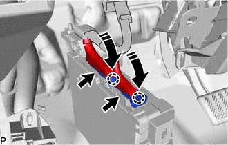
|
|
Install in this Direction |
Connect the 2 connectors and pull down the 2 lock levers to engage the 2 claws and lock the connector as shown in the illustration.
- NOTICE:
-
Be sure to connect the connector securely.
Engage the clamp.
Engage the clamp.
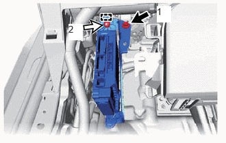

|
Bolt |

|
Nut |
Engage the clamp.
Install the bolt and nut.
- Torque:
- 8.0 N*m (82 kgf*cm, 71 in.*lbf)
- HINT:
-
Tighten the bolt and nut in the order shown in the illustration.
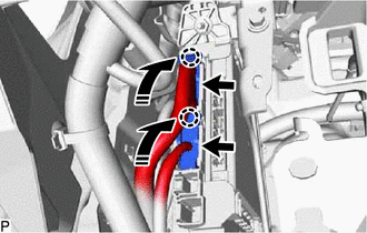
|
|
Install in this Direction |
Connect the 2 connectors and raise the 2 lock levers to engage the 2 claws and lock the connector as shown in the illustration.
- NOTICE:
-
Be sure to connect the connector securely.
Engage the clamp.
Connect each connector.
5.INSTALL POWER DISTRIBUTION BOX ASSEMBLY WITH MAIN BODY ECU (except NR Series Engine)
|
|
Install in this Direction |
Connect the 2 connectors and pull down the 2 lock levers to engage the 2 claws and lock the connector as shown in the illustration.
- NOTICE:
-
Be sure to connect the connector securely.
Engage the clamp.
Engage the clamp.
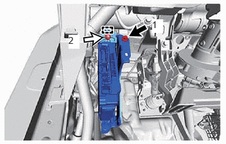
|
|
Bolt |
|
|
Nut |
Engage the clamp.
Install the bolt and nut.
- Torque:
- 8.0 N*m (82 kgf*cm, 71 in.*lbf)
- HINT:
-
Tighten the bolt and nut in the order shown in the illustration.
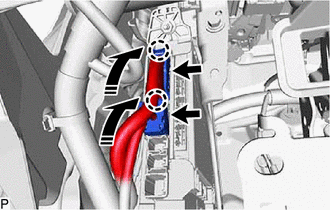
|
|
Install in this Direction |
Connect the 2 connectors and raise the 2 lock levers to engage the 2 claws and lock the connector as shown in the illustration.
- NOTICE:
-
Be sure to connect the connector securely.
Engage the clamp.
Connect each connector.
55308B
6.INSTALL NO. 3 INSTRUMENT PANEL TO COWL BRACE SUB-ASSEMBLY (w/o Knee Airbag)
Install the No. 3 instrument panel to cowl brace sub-assembly with the bolt and nut.
- Torque:
- Bolt : 10 N*m (102 kgf*cm, 7 ft.*lbf)
- Nut : 6.0 N*m (61 kgf*cm, 53 in.*lbf)
55308B
7.INSTALL NO. 3 INSTRUMENT PANEL TO COWL BRACE SUB-ASSEMBLY (w/ Knee Airbag)
Install the No. 3 instrument panel to cowl brace sub-assembly with the 2 bolts and nut.
- Torque:
- Bolt : 10 N*m (102 kgf*cm, 7 ft.*lbf)
- Nut : 6.0 N*m (61 kgf*cm, 53 in.*lbf)
55432B
8.INSTALL LOWER INSTRUMENT PANEL FINISH PANEL
53601
9.CONNECT HOOD LOCK CONTROL LEVER SUB-ASSEMBLY
55606
10.INSTALL NO. 1 INSTRUMENT PANEL UNDER COVER SUB-ASSEMBLY
55317E
11.INSTALL NO. 1 INSTRUMENT SIDE PANEL
62312B
12.CONNECT FRONT DOOR OPENING TRIM WEATHERSTRIP LH
62112A
13.INSTALL COWL SIDE TRIM SUB-ASSEMBLY LH
67914
14.INSTALL FRONT DOOR SCUFF PLATE LH
15.CONNECT CABLE TO NEGATIVE AUXILIARY BATTERY TERMINAL
for NR Series: Click hereGeneral>MAINTENANCE>NR Series BATTERY>INSTALLATION202304,999999,_V1,_080956,_0392375,RM100000002BCCN_03_0002,
for 8ZR-FXE: Click hereGeneral>MAINTENANCE>8ZR-FXE AUXILIARY BATTERY>INSTALLATION202304,999999,_V1,_080956,_0392376,RM100000002ACL8_01_0029,
for M15B-FKS: Click hereGeneral>MAINTENANCE>M15B-FKS BATTERY>INSTALLATION202304,999999,_V1,_080956,_0453685,RM100000002BCCF_03_0002,
for M15C-FKS: Click hereGeneral>MAINTENANCE>M15C-FKS BATTERY>INSTALLATION202304,999999,_V1,_080956,_0453686,RM100000002BCCG_03_0002,
for M20A-FKS: Click hereGeneral>MAINTENANCE>M20A-FKS BATTERY>INSTALLATION202304,999999,_V1,_080956,_0470107,RM100000002BCCI_03_0002,
for M20E-FKS: Click hereGeneral>MAINTENANCE>M20E-FKS BATTERY>INSTALLATION202304,999999,_V1,_080956,_0474497,RM100000002BCCK_03_0002,
for M20C-FKS: Click hereGeneral>MAINTENANCE>M20C-FKS BATTERY>INSTALLATION202304,999999,_V1,_080956,_0484846,RM100000002BCCJ_03_0002,