8ZR-FXE INTAKE / EXHAUST INTAKE MANIFOLD INSTALLATION
PROCEDURE

 1.INSTALL STUD BOLT (w/ Stud Bolt)
- HINT:
-
If a stud bolt is deformed or the threads are damaged, replace it.
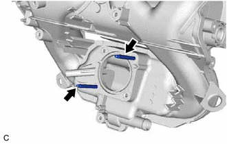
Using an E6 "TORX" socket wrench, install the 2 stud bolts to the intake manifold.
- Torque:
- 5.0 N*m (51 kgf*cm, 44 in.*lbf)
17177
2.INSTALL NO. 1 INTAKE MANIFOLD TO HEAD GASKET
Install a new No. 1 intake manifold to head gasket to the intake manifold.
17111
3.INSTALL INTAKE MANIFOLD
Temporarily install the intake manifold to the cylinder head sub-assembly with the 3 bolts and 2 nuts.
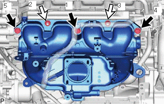

|
Bolt |

|
Nut |
Tighten the 3 bolts and 2 nuts in the order shown in the illustration.
- Torque:
- 28 N*m (286 kgf*cm, 21 ft.*lbf)
4.CONNECT WATER BY-PASS HOSE
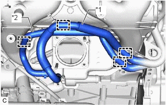
| *1 | Water By-Pass Hose |
| *2 | No. 2 Water By-pass Hose |
Engage the 2 hose clamps to connect the No. 2 water by-pass hose to the intake manifold.
Engage the 2 hose clamps to connect the water by-pass hose to the intake manifold.
23827A
5.CONNECT NO. 2 FUEL VAPOR FEED HOSE
Engage the 2 hose clamps.
Connect the No. 2 fuel vapor feed hose to the intake manifold.
16296
6.CONNECT NO. 8 WATER BY-PASS HOSE
Connect the No. 8 water by-pass hose to the No. 3 water by-pass pipe and slide the clip to secure it.
Engage the 2 hose clamps.
7.CONNECT ENGINE COVER BRACKET
Connect the engine cover bracket to the intake manifold with the bolt.
- Torque:
- 8.0 N*m (82 kgf*cm, 71 in.*lbf)
82121
8.CONNECT ENGINE WIRE
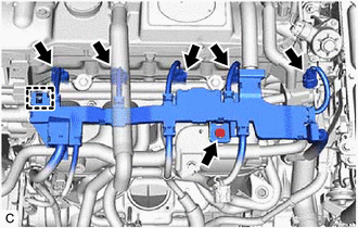
Engage the clamp and connect the engine wire with the bolt.
- Torque:
- 8.0 N*m (82 kgf*cm, 71 in.*lbf)
Connect the 4 fuel injector assembly connectors and purge valve (purge VSV) connector.
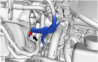
Connect the wire harness bracket with the bolt.
- Torque:
- 8.0 N*m (82 kgf*cm, 71 in.*lbf)
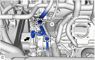
Connect the engine water pump assembly connector.
Engage the 2 clamps.
12261
9.CONNECT VENTILATION HOSE
Connect the ventilation hose to the intake manifold and slide the clip to secure it.
89421
10.INSTALL E.F.I. VACUUM SENSOR ASSEMBLY (MANIFOLD ABSOLUTE PRESSURE SENSOR)
Install the E.F.I. vacuum sensor assembly (manifold absolute pressure sensor) to the intake manifold with the bolt.
- Torque:
- 7.0 N*m (71 kgf*cm, 62 in.*lbf)
Connect the vacuum hose to the intake manifold.
Connect the E.F.I. vacuum sensor assembly (manifold absolute pressure sensor) connector.
25610
11.INSTALL EGR PIPE ASSEMBLY
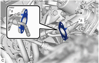
| *a | Claw |
Install a new EGR pipe gasket to the EGR valve assembly.
- NOTICE:
-
Make sure that the claws of the EGR pipe gasket are toward the EGR valve assembly side.
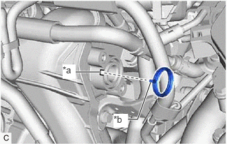
| *a | Groove |
| *b | Protrusion |
Install a new inlet EGR gasket to the intake manifold.
- HINT:
-
Align the protrusion of the inlet EGR gasket with the groove of the intake manifold.
Install the EGR pipe assembly to the intake manifold and EGR valve assembly with the 4 bolts.
- Torque:
- 8.5 N*m (87 kgf*cm, 75 in.*lbf)
17751
12.INSTALL INLET NO. 1 AIR CLEANER
Install the inlet No. 1 air cleaner to the intake manifold with the 2 bolts.
- Torque:
- 4.0 N*m (41 kgf*cm, 35 in.*lbf)
17771A
13.INSTALL AIR CLEANER BRACKET
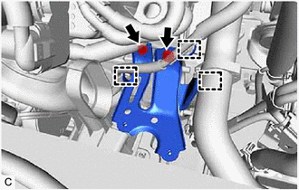
Engage the 2 wire harness clamps and the hose clamp, and attach the air cleaner bracket to the cylinder block sub-assy, the air conditioner conditioning wire, and the No. 1 radiator hose with 2 bolts.
- Torque:
- 12 N*m (122 kgf*cm, 9 ft.*lbf)
17701
14.INSTALL AIR CLEANER CASE SUB-ASSEMBLY
Install the air cleaner case sub-assembly to the air cleaner bracket with the 2 bolts.
- Torque:
- 4.0 N*m (41 kgf*cm, 35 in.*lbf)
17801
15.INSTALL AIR CLEANER FILTER ELEMENT SUB-ASSEMBLY
Install the air cleaner filter element sub-assembly to the air cleaner case sub-assembly.
17752
16.INSTALL INLET NO. 2 AIR CLEANER
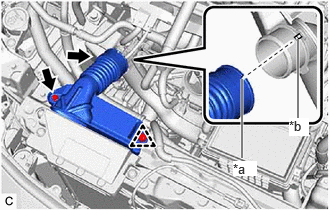
| *a | Groove |
| *b | Protrusion |
Install the air cleaner inlet No. 2 to the air cleaner inlet No. 1 and the radiator support sub-assembly UPR with bolt and clips.
- HINT:
-
Align the protrusion of the inlet No. 1 air cleaner with the groove of the inlet No. 2 air cleaner.
Tighten the bolt.
- Torque:
- 4.0 N*m (41 kgf*cm, 35 in.*lbf)
Install the clip.
53289A
17.INSTALL RADIATOR SUPPORT OPENING COVER
22210
18.INSTALL THROTTLE BODY ASSEMBLY