THEFT DETERRENT / KEYLESS ENTRY THEFT DETERRENT SYSTEM(except NR Series Engine) Security Horn Circuit
DESCRIPTION
When the theft deterrent system is switched from the armed state to the alarm sounding state, the main body ECU (multiplex network body ECU) transmits a signal to cause the security horn to sound at intervals of 0.4 seconds.
WIRING DIAGRAM

CAUTION / NOTICE / HINT
- NOTICE:
- ·
Inspect the fuses for circuits related to this system before performing the following procedure.
·If the main body ECU (multiplex network body ECU) is replaced, refer to the Service Bulletin.
PROCEDURE
According to the display on the GTS, perform the Active Test.
- Body Electrical > Main Body > Active Test
-
Tester Display Measurement Item Control Range Diagnostic Note Security Horn Security horn assembly ON or OFF -
- Body Electrical > Main Body > Active Test
-
Tester Display Security Horn - 50004 449 3
- OK:
The security horn assembly sounds and stops correctly when operated through the GTS.
- Result:
Proceed to OK NG
OK
NG
- Result:
Proceed to OK NG
OK
NG
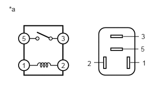
| *a | Component without harness connected
(S-HORN RELAY) |
Remove the S-HORN relay.
Measure the resistance according to the value(s) in the table below
- Standard Resistance:
Tester Connection Condition Specified Condition S-HORN relay terminal 3 - S-HORN relay terminal 5 Auxiliary battery voltage is applied between security warning relay (S-HORN) terminals 2 - 1 Below 1 Ω S-HORN relay terminal 3 - S-HORN relay terminal 5 Auxiliary battery voltage is not applied between security warning relay (S-HORN) terminals 2 - 1 10 kΩ or higher
- Result:
Proceed to OK NG
OK
NG
Remove the main body ECU (multiplex network body ECU).
Connect the power distribution box assembly connectors.
Measure the resistance according to the value(s) in the table below.
- Standard Resistance:
Tester Connection Condition Specified Condition S-HORN relay terminal 2 - MB-24 (SH) Always Below 1 Ω S-HORN relay terminal 2 or MB-24 (SH) - Other terminals and body ground Always 10 kΩ or higher
- Result:
Proceed to OK NG
OK
NG
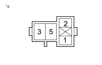
| *a | Front view of wire harness connector
(to S-HORN Relay) |
Remove the S-HORN relay.
Measure the voltage according to the value(s) in the table below.
- Standard Voltage:
Tester Connection Condition Specified Condition S-HORN relay terminal 1 - Body ground Ignition switch off*1
Always*211 to 14 V S-HORN relay terminal 5 - Body ground Ignition switch off*1
Always*211 to 14 V
*1: for HV Model
*2: for Gasoline Model
- Result:
Proceed to OK NG
OK
NG
Disconnect the A16 security horn assembly connector.
Measure the resistance according to the value(s) in the table below.
- Standard Resistance:
Tester Connection Condition Specified Condition S-HORN terminal 3 - A16-1 Always Below 1 Ω S-HORN relay terminal 3 or A16-1 - Other terminals and body ground Always 10 kΩ or higher
- Result:
Proceed to OK NG
OK
NG
Disconnect the 10F power distribution box assembly connector.
Measure the resistance according to the value(s) in the table below.
- Standard Resistance:
Tester Connection Condition Specified Condition S-HORN relay terminal 2 - 10F-14 Always Below 1 Ω S-HORN relay terminal 2 or 10F-14 - Other terminals and body ground Always 10 kΩ or higher
- Result:
Proceed to OK NG
OK
NG