☰ Toyota Levin Hybrid☰ فهرستVehicle Interior › THEFT DETERRENT / KEYLESS ENTRY › THEFT DETERRENT SYSTEM(except NR Series Engine)
RM3660EC
_58
Vehicle Interior
_080747
THEFT DETERRENT / KEYLESS ENTRY
_0588948
THEFT DETERRENT SYSTEM(except NR Series Engine)
J
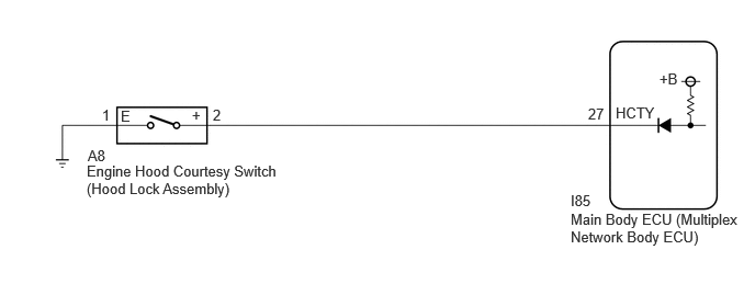
THEFT DETERRENT / KEYLESS ENTRY THEFT DETERRENT SYSTEM(except NR Series Engine) Engine Hood Courtesy Switch Circuit
DESCRIPTION
The engine hood courtesy switch is installed together with the hood lock. This switch turns on when the engine hood is closed and turns off when the engine hood is opened.
WIRING DIAGRAM
5.417,2 7.083,2.375
1.667,0.375
10
false
Main Body ECU (Multiplex Network Body ECU)
0.823,1.542 2.656,1.927
1.833,0.385
10
false
Engine Hood Courtesy Switch (Hood Lock Assembly)
5.844,0.99 6.281,1.219
0.438,0.229
10
false
HCTY
5.583,1 5.813,1.198
0.229,0.198
10
false
27
2.021,1.01 2.458,1.24
0.438,0.229
10
false
2
0.969,1.01 1.406,1.24
0.438,0.229
10
false
1
5.417,1.823 5.719,2.01
0.302,0.188
10
false
I85
0.833,1.396 1.271,1.625
0.438,0.229
10
false
A8
6.26,0.667 6.49,0.854
0.229,0.188
10
false
+B
1.823,1.01 2.26,1.24
0.438,0.229
10
false
+
1.146,1.021 1.583,1.25
0.438,0.229
10
false
E
CAUTION / NOTICE / HINT
- NOTICE:
-
If the main body ECU (multiplex network body ECU) is replaced, refer to the Service Bulletin.
PROCEDURE
1.READ VALUE USING GTS (HOOD COURTESY SWITCH STATUS)
a.
According to the display on the GTS, read the Data List.
- Body Electrical > Main Body > Data List
-
Tester Display Measurement Item Range Normal Condition Diagnostic Note Hood Courtesy Switch Status Engine hood courtesy switch ON or OFF ON: Engine hood open
OFF: Engine hood closed-
- Body Electrical > Main Body > Data List
-
Tester Display Hood Courtesy Switch Status - 50003 449 37
- OK:
The indicator on the GTS switches between ON and OFF in accordance with the engine hood courtesy switch (hood lock assembly) status.
- Result:
Proceed to OK NG
OK
PROCEED TO NEXT SUSPECTED AREA SHOWN IN PROBLEM SYMPTOMS TABLE
NG
2.CHECK HARNESS AND CONNECTOR (ENGINE HOOD COURTESY SWITCH (HOOD LOCK ASSEMBLY) - MAIN BODY ECU (MULTIPLEX NETWORK BODY ECU) AND BODY GROUND)
2.CHECK HARNESS AND CONNECTOR (ENGINE HOOD COURTESY SWITCH (HOOD LOCK ASSEMBLY) - MAIN BODY ECU (MULTIPLEX NETWORK BODY ECU) AND BODY GROUND)
a.
Disconnect the I85 main body ECU (multiplex network body ECU) connector.
b.
Measure the resistance according to the value(s) in the table below.
- Standard Resistance:
Tester Connection Condition Specified Condition A8-2 (+) - I85-27 (HCTY) Always Below 1 Ω A8-1 (E) - Body ground Always Below 1 Ω A8-2 (+) or I85-27 (HCTY) - Other terminals and body ground Always 10 kΩ or higher
- Result:
Proceed to OK NG
OK
3.INSPECT ENGINE HOOD COURTESY SWITCH (HOOD LOCK ASSEMBLY)
NG
REPAIR OR REPLACE HARNESS OR CONNECTOR
3.INSPECT ENGINE HOOD COURTESY SWITCH (HOOD LOCK ASSEMBLY)
- Result:
Proceed to OK NG
OK
REPLACE MAIN BODY ECU (MULTIPLEX NETWORK BODY ECU)
NG
REPLACE ENGINE HOOD COURTESY SWITCH (HOOD LOCK ASSEMBLY)