RM3660EC
_57
Power Source / Network
_080757
8ZR-FXE BATTERY / CHARGING
_0393175
CHARGING SYSTEM
U
8ZR-FXE BATTERY / CHARGING CHARGING SYSTEM TERMINALS OF ECU
2.406,0.313 2.823,0.573
0.417,0.26
4.583,0.302 5,0.563
0.417,0.26
2.458,0.375 2.917,0.573
0.458,0.198
10
false
A147
4.75,0.354 5.208,0.552
0.458,0.198
10
false
I3
0.104,0.073 0.417,0.271
0.313,0.198
10
false
*a
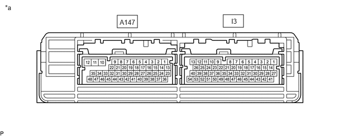
| *a | Hybrid Vehicle Control ECU | - | - |
- HINT:
-
The standard normal voltage between each pair of hybrid vehicle control ECU terminals is shown in the table below. The appropriate conditions for checking each pair of terminals are also indicated. The result of checks should be compared with the standard normal voltage for that pair of terminals, displayed in the Specified Condition column. The illustration above can be used as a reference to identify the hybrid vehicle control ECU terminal locations.
| Terminal No. (Symbol) | Terminal Description | Condition | Specified Condition |
|---|---|---|---|
| A147-1 (HMCL) - I3-1 (E1) | Communication signal | Power switch on (IG) | Pulse generation
(Waveform 1) |
| A147-2 (HMCH) - I3-1 (E1) | Communication signal | Power switch on (IG) | Pulse generation
(Waveform 1) |
| A147-16 (LIN3) - I3-1 (E1) | LIN communication signal | Power switch on (READY) | Pulse generation |
| I3-10 (MREL) - I3-1 (E1) | IGCT-MAIN NO. 1 relay | Power switch on (IG) | 11 to 14 V |
a.
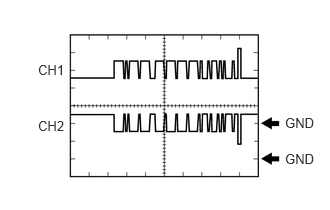
Oscilloscope waveforms
- HINT:
-
Oscilloscope waveform samples are provided here for informational purposes. Noise and fluttering waveforms have been omitted.
i.
2.969,1.198 3.427,1.396
0.458,0.198
10
GND
2.969,1.573 3.427,1.771
0.458,0.198
10
GND
0.396,0.646 0.854,0.844
0.458,0.198
10
CH1
0.396,1.229 0.854,1.427
0.458,0.198
10
CH2
Waveform 1 (Communication signal)
| Item | Content |
|---|---|
| Terminal | CH1: A147-2 (HMCH) - I3-1 (E1)
CH2: A147-1 (HMCL) - I3-1 (E1) |
| Equipment Setting | 1 V/DIV., 50 μs./DIV. |
| Condition | Power switch on (IG) |
- HINT:
-
The waveform will vary depending on the content of the digital communication (digital signal).