☰ Toyota Levin Hybrid☰ فهرستADAS / AD › ADVANCED DRIVER ASSISTANCE SYSTEM › AUTOMATIC HIGH BEAM SYSTEM(except NR Series Engine)
RM3660EC
_95
ADAS / AD
_139716
ADVANCED DRIVER ASSISTANCE SYSTEM
_0584195
AUTOMATIC HIGH BEAM SYSTEM(except NR Series Engine)
J
ADVANCED DRIVER ASSISTANCE SYSTEM AUTOMATIC HIGH BEAM SYSTEM(except NR Series Engine) Automatic High Beam Switch Circuit
DESCRIPTION
The main body ECU (multiplex network body ECU) detects the ON/OFF signal of the auto high beam switch.
WIRING DIAGRAM
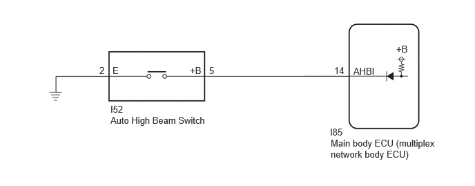
1.5,0.979 1.854,1.188
0.354,0.208
10
false
2
1.698,0.979 2.052,1.188
0.354,0.208
10
false
E
2.865,0.979 3.219,1.188
0.354,0.208
10
false
+B
3.156,0.979 3.51,1.188
0.354,0.208
10
false
5
1.667,1.563 2.021,1.771
0.354,0.208
10
false
I52
1.667,1.729 3.479,2.115
1.813,0.385
10
false
Auto High Beam Switch
4.979,1.906 5.594,2.125
0.615,0.219
10
false
I85
4.99,2.073 6.635,2.5
1.646,0.427
10
false
Main body ECU (multiplex network body ECU)
5.333,0.99 5.688,1.198
0.354,0.208
10
false
AHBI
5.979,0.656 6.333,0.865
0.354,0.208
10
false
+B
5.042,0.979 5.396,1.188
0.354,0.208
10
false
14
CAUTION / NOTICE / HINT
- NOTICE:
-
Before replacing the main body ECU (multiplex network body ECU), refer to Service Bulletin.*
*: w/ Smart Entry and Start System
PROCEDURE
1.READ VALUE USING GTS
a.
Read the Data List according to the display on the GTS.
- Body Electrical > Main Body > Data List
-
Tester Display Measurement Item Range Normal Condition Diagnostic Note Auto High Beam Main Switch Automatic high beam switch signal OFF or ON OFF: Automatic high beam switch not pressed
ON: Automatic high beam switch pressed-
- Body Electrical > Main Body > Data List
-
Tester Display Auto High Beam Main Switch - 50003 449 107
- OK:
Normal conditions listed above are displayed.
- Result:
Proceed to OK NG
OK
PROCEED TO NEXT SUSPECTED AREA SHOWN IN PROBLEM SYMPTOMS TABLE
NG
2.INSPECT AUTO HIGH BEAM SWITCH
2.INSPECT AUTO HIGH BEAM SWITCH
- Result:
Proceed to OK NG
OK
3.CHECK HARNESS AND CONNECTOR (AUTO HIGH BEAM SWITCH - MAIN BODY ECU (MULTIPLEX NETWORK BODY ECU) AND BODY GROUND)
NG
REPLACE AUTO HIGH BEAM SWITCH
3.CHECK HARNESS AND CONNECTOR (AUTO HIGH BEAM SWITCH - MAIN BODY ECU (MULTIPLEX NETWORK BODY ECU) AND BODY GROUND)
a.
Disconnect the I85 main body ECU (multiplex network body ECU) connector.
b.
Measure the resistance according to the value(s) in the table below.
- Standard Resistance:
Tester Connection Condition Specified Condition I52-5 (+B) - I85-14 (AHBI) Always Below 1 Ω I52-5 (+B) or I85-14 (AHBI) - Body ground Always 10 kΩ or higher I52-2 (E) - Body ground Always Below 1 Ω
- Result:
Proceed to OK NG
OK
REPLACE MAIN BODY ECU (MULTIPLEX NETWORK BODY ECU)
for LHD: Click herePower Source / Network>POWER DISTRIBUTION>MAIN BODY ECU>REMOVAL202304,202502,_57,_080742,_0392832,RM100000002B2HJ,202502,999999,_57,_080742,_0392832,RM100000002RPNZ,
for RHD: Click here
NG
REPAIR OR REPLACE HARNESS OR CONNECTOR