☰ Toyota Levin Hybrid☰ فهرستDrivetrain › PA10/PB10 HYBRID TRANSMISSION / TRANSAXLE › PATTERN SELECT SWITCH
RM3660EC
_52
Drivetrain
_138496
PA10/PB10 HYBRID TRANSMISSION / TRANSAXLE
_0583547
PATTERN SELECT SWITCH
G
PA10/PB10 HYBRID TRANSMISSION / TRANSAXLE PATTERN SELECT SWITCH INSPECTION
PROCEDURE

 84970
1.INSPECT COMBINATION SWITCH ASSEMBLY
84970
1.INSPECT COMBINATION SWITCH ASSEMBLY
a.
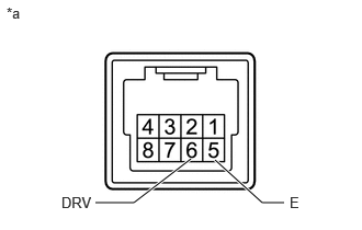
Inspect the DRIVE MODE switch:
i.
0.906,1.927 1.271,1.927
1.271,1.927 1.813,1.51
true
2.698,1.927 2.49,1.927
2.49,1.927 2.042,1.521
true
0.063,0.042 0.375,0.198
0.313,0.156
10
false
*a
2.75,1.844 2.969,2.073
0.219,0.229
10
false
E
0.583,1.844 0.938,2.042
0.354,0.198
10
false
DRV
| *a | Component without harness connected
(Combination Switch Assembly) |
Measure the resistance according to the value(s) in the table below.
- Standard Resistance:
Tester Connection Condition Specified Condition 6 (DRV) - 5 (E) Pressed Below 50 Ω Not pressed 10 kΩ or higher
If the result is not as specified, replace the combination switch assembly.
b.
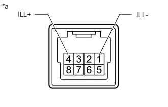
Inspect the illumination:
i.
0.708,0.292 0.979,0.292
0.979,0.292 1.396,1.125
true
2.698,0.292 2.448,0.292
2.448,0.292 2.031,1.125
true
0.042,0.042 0.354,0.198
0.313,0.156
10
false
*a
0.365,0.208 0.979,0.406
0.615,0.198
10
false
ILL+
2.792,0.219 3.406,0.417
0.615,0.198
10
false
ILL-
| *a | Component without harness connected
(Combination Switch Assembly) |
Apply auxiliary battery voltage between the terminals of the switch and check the illumination condition of the combination switch assembly.
- Standard:
Measurement Condition Specified Condition Auxiliary battery positive (+) → 4 (ILL+) Illuminates Auxiliary battery negative (-) → 1 (ILL-)
If the result is not as specified, replace combination switch assembly.