8ZR-FXE ENGINE CONTROL RELAY ON-VEHICLE INSPECTION
PROCEDURE

 85910
1.INSPECT CIRCUIT OPENING RELAY ASSEMBLY (C/OPN)
85910
1.INSPECT CIRCUIT OPENING RELAY ASSEMBLY (C/OPN)
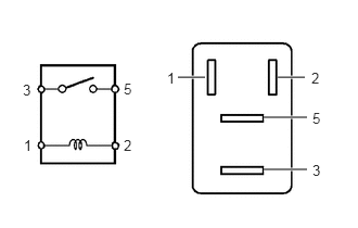
Measure the resistance according to the value(s) in the table below.
- Standard Resistance:
Tester Connection Condition Specified Condition 3 - 5 Auxiliary battery voltage is not applied between terminals 1 and 2 10 kΩ or higher Auxiliary battery voltage is applied between terminals 1 and 2 Below 1 Ω
If the result is not as specified, replace the circuit opening relay assembly (C/OPN).
89561F
2.INSPECT NO. 1 ELECTRONIC FUEL INJECTION MAIN RELAY (EFI-MAIN NO.1)
Measure the resistance according to the value(s) in the table below.
- Standard Resistance:
Tester Connection Condition Specified Condition 3 - 5 Auxiliary battery voltage is not applied between terminals 1 and 2 10 kΩ or higher Auxiliary battery voltage is applied between terminals 1 and 2 Below 1 Ω
If the result is not as specified, replace the No. 1 electronic fuel injection main relay (EFI-MAIN NO.1).
89561G
3.INSPECT NO. 2 ELECTRONIC FUEL INJECTION MAIN RELAY (EFI-MAIN NO.2)
Measure the resistance according to the value(s) in the table below.
- Standard Resistance:
Tester Connection Condition Specified Condition 3 - 5 Auxiliary battery voltage is not applied between terminals 1 and 2 10 kΩ or higher Auxiliary battery voltage is applied between terminals 1 and 2 Below 1 Ω
If the result is not as specified, replace the No. 2 electronic fuel injection main relay (EFI-MAIN NO.2).
89561H
4.INSPECT NO. 3 ELECTRONIC FUEL INJECTION MAIN RELAY (EFI-MAIN NO.3)
Measure the resistance according to the value(s) in the table below.
- Standard Resistance:
Tester Connection Condition Specified Condition 3 - 5 Auxiliary battery voltage is not applied between terminals 1 and 2 10 kΩ or higher Auxiliary battery voltage is applied between terminals 1 and 2 Below 1 Ω
If the result is not as specified, replace the No. 3 electronic fuel injection main relay (EFI-MAIN NO.3).
28371L
5.INSPECT IGP RELAY (IGP-MAIN)
Measure the resistance according to the value(s) in the table below.
- Standard Resistance:
Tester Connection Condition Specified Condition 3 - 5 Auxiliary battery voltage is not applied between terminals 1 and 2 10 kΩ or higher Auxiliary battery voltage is applied between terminals 1 and 2 Below 1 Ω
If the result is not as specified, replace the IGP relay (IGP-MAIN).