HEATING / AIR CONDITIONING COMPRESSOR(for 8ZR-FXE) INSTALLATION
PROCEDURE

 1.ADJUST COMPRESSOR OIL
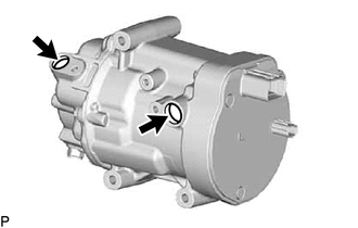
When replacing the compressor with motor assembly with a new one, gradually discharge the inert gas from the service valve, and drain the following amount of oil from the new compressor with motor assembly before installation.
- Standard:
(Oil capacity inside the new compressor with motor assembly: 110 to 125 cc (3.72 to 4.22 fl. oz)) - (Remaining oil amount in the removed compressor with motor assembly) - 65 cc (2.20 fl.oz) = (Oil amount to be removed from the new compressor)
- NOTICE:
- ·
When checking the compressor oil level, observe the precautions on the cooler removal/installation.
·If a new compressor with motor assembly is installed without removing some oil, there will be too much oil in the system due to the oil remaining in the pipes of the vehicle. Excessive oil in the system prevents heat exchange in the refrigeration cycle and causes ineffective cooling.
·If the amount of oil remaining in the old compressor with motor assembly is too small, check the air conditioning system for oil leaks.
·Be sure to use ND-OIL 11 or equivalent compressor oil. If any compressor oil other than ND-OIL 11 is used, compressor with motor assembly insulation performance may decrease, resulting in leakage of electric power.
·Make sure to drain compressor oil from the intake port.
·Make sure to add compressor oil from the intake port.
·If the amount of oil from the removed compressor with motor assembly plus an additional 65 cc (2.20 fl.oz) is then greater than the amount of oil in a new compressor with motor assembly, do not drain the compressor oil from the new compressor with motor assembly.
·When it is not possible to confirm the amount of oil in the system such as when compressor oil is spilt due to damage caused by a vehicle collision, etc., install a new compressor without draining any oil. If also replacing the cooler condenser assembly, do not add the supplied oil (40 cc (1.35 fl.oz)).
88370
2.INSTALL COMPRESSOR WITH MOTOR ASSEMBLY
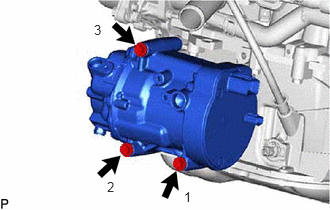
Install the compressor with motor assembly with the 3 bolts.
- Torque:
- 25 N*m (255 kgf*cm, 18 ft.*lbf)
- HINT:
-
Tighten the bolts in the order shown in the illustration.
Install the bracket with the bolt.
- Torque:
- 8.0 N*m (82 kgf*cm, 71 in.*lbf)
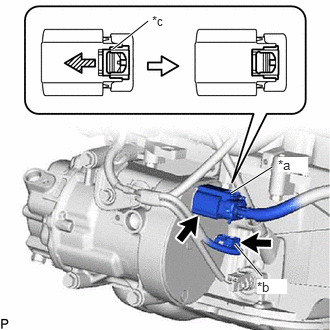
| *a | Connector (A) |
| *b | Connector (B) |
| *c | Green-colored Lock |

|
Slide |
Connect the connector (B).
Remove the insulating tape from the connector (A).
Connect the connector (A) and slide the green-colored lock as shown in the illustration to securely lock it.
- CAUTION:
-
Make sure to wear insulated gloves.
- NOTICE:
-
Make sure that the connector is connected securely.
88704
3.CONNECT SUCTION HOSE SUB-ASSEMBLY
Remove the vinyl tape from the suction hose sub-assembly.
Sufficiently apply compressor oil to a new O-ring and the fitting surface of the compressor with motor assembly.
- Compressor Oil:
ND-OIL 11 or equivalent
Install the O-ring to the suction hose sub-assembly.
- NOTICE:
-
Keep the O-ring and O-ring fitting surface free of foreign matter.
Connect the suction hose sub-assembly to the compressor with motor assembly with the bolt.
- Torque:
- 9.8 N*m (100 kgf*cm, 87 in.*lbf)
88703
4.CONNECT DISCHARGE HOSE SUB-ASSEMBLY
Remove the vinyl tape from the discharge hose sub-assembly.
Sufficiently apply compressor oil to a new O-ring and the fitting surface of the compressor with motor assembly.
- Compressor Oil:
ND-OIL 11 or equivalent
Install the O-ring to the discharge hose sub-assembly.
- NOTICE:
-
Keep the O-ring and O-ring fitting surface free of foreign matter.
Connect the discharge hose sub-assembly to the compressor with motor assembly with the bolt.
- Torque:
- 9.8 N*m (100 kgf*cm, 87 in.*lbf)
17751
5.INSTALL INLET NO. 1 AIR CLEANER
17771A
6.INSTALL AIR CLEANER BRACKET
17701
7.INSTALL AIR CLEANER CASE SUB-ASSEMBLY
17801
8.INSTALL AIR CLEANER FILTER ELEMENT SUB-ASSEMBLY
9.INSTALL AIR CLEANER HOSE ASSEMBLY
17705
10.INSTALL AIR CLEANER CAP SUB-ASSEMBLY
17752
11.INSTALL INLET NO. 2 AIR CLEANER
53289A
12.INSTALL RADIATOR SUPPORT OPENING COVER (for TFTM Made)
53289A
13.INSTALL RADIATOR SUPPORT OPENING COVER (for GTMC Made)
G3834
14.INSTALL SERVICE PLUG GRIP
15.CHARGE AIR CONDITIONING SYSTEM WITH REFRIGERANT
16.WARM UP COMPRESSOR