8ZR-FXE EMISSION CONTROL PURGE VALVE INSTALLATION
CAUTION / NOTICE / HINT
- NOTICE:
-
When installing the fuel vapor feed hose, hold the purge valve body securely in place by hand.
PROCEDURE

 17650G
1.INSTALL PURGE VALVE (PURGE VSV)
17650G
1.INSTALL PURGE VALVE (PURGE VSV)
Install the purge valve (purge VSV) to the No. 3 water by-pass pipe with the screw.
- Torque:
- 3.4 N*m (35 kgf*cm, 30 in.*lbf)
Install the purge valve (purge VSV) with No. 3 water by-pass pipe to the camshaft housing sub-assembly with the bolt.
- Torque:
- 28 N*m (286 kgf*cm, 21 ft.*lbf)
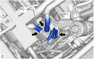
| *1 | No. 1 Fuel Vapor Feed Hose |
| *2 | No. 2 Fuel Vapor Feed Hose |
Connect the No. 2 fuel vapor feed hose to the purge valve (purge VSV).
Connect the No. 1 fuel vapor feed hose to the purge valve (purge VSV).
Connect the purge valve (purge VSV) connector.
16297
2.CONNECT NO. 9 WATER BY-PASS HOSE
Connect the No. 9 water by-pass hose to the No. 3 water by-pass pipe and slide the clip to secure it.
16296
3.CONNECT NO. 8 WATER BY-PASS HOSE
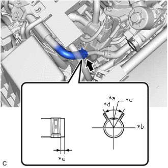
| *a | Up |
| *b | LH |
| *c | Paint Mark |
| *d | 60° |
| *e | 2 to 7 mm (0.0787 to 0.276 in.) |
Connect the No. 8 water by-pass hose to the No. 3 water by-pass pipe and slide the clip to secure it.
- HINT:
-
Engage the clip within the area shown in the illustration.
25610
4.INSTALL EGR PIPE ASSEMBLY
5.ADD ENGINE COOLANT (for Engine)
6.INSPECT FOR COOLANT LEAK (for Engine)