8ZR-FXE ENGINE MECHANICAL CYLINDER BLOCK REASSEMBLY
PROCEDURE

 15708
1.INSTALL NO. 1 OIL NOZZLE SUB-ASSEMBLY
15708
1.INSTALL NO. 1 OIL NOZZLE SUB-ASSEMBLY
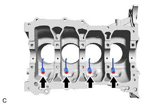
Using a 5 mm hexagon socket wrench, install the 4 No. 1 oil nozzle sub-assemblies to the cylinder block sub-assembly with the 4 bolts.
- Torque:
- 10 N*m (102 kgf*cm, 7 ft.*lbf)
13101
2.INSTALL PISTON
- HINT:
-
Perform this procedure only when replacement of the piston pin hole snap ring (rear side) is necessary.
Using a screwdriver, install a new piston pin hole snap ring (rear side) at one end of the piston pin hole.
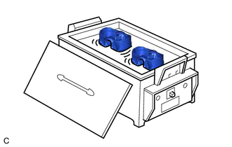
Gradually heat the piston to between approximately 80 and 90°C (176 and 194°F).
- CAUTION:
-
Be sure to wear protective gloves.
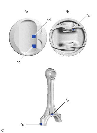
| *a | Upper Side |
| *b | Lower Side |
| *c | Front Mark |
| *d | Piston Pin Bore Diameter Mark |
| *e | Connecting Rod Small End Bush Bore Diameter Mark |
Align the front marks of the piston and connecting rod, insert the connecting rod into the piston, and then push in the piston pin with your thumb until the piston pin comes into contact with the snap ring.
- HINT:
-
The piston and piston pin are a matched set.
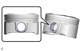
| *a | Cutout |
Using a screwdriver, install a new piston pin hole snap ring at the other end of the piston pin hole.
- NOTICE:
-
Make sure that the end gap of the snap ring is not aligned with the cutout of the piston pin hole.
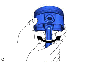
Check the fitting condition between the piston and piston pin by trying to move the piston back and forth on the piston pin.
- HINT:
-
If abnormal movement is felt, replace the piston and piston pin as a set.
13011
3.INSTALL PISTON RING SET

| *1 | Upper Side Rail |
| *2 | Oil Ring Expander |
| *3 | Lower Side Rail |
Install the oil ring expander, upper side rail and lower side rail to the piston by hand.
- NOTICE:
-
When installing the upper side rail and lower side rail, the ends of the oil ring expander may overlap. If this occurs, the upper side rail or lower side rail may move out of its groove.
Check that the ends of the oil ring expander are not overlapping and that the upper side rail and lower side rail are securely installed into the groove.
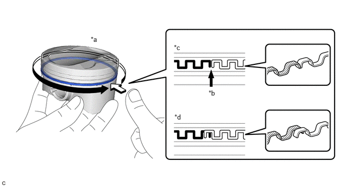
| *a | Press around the circumference | *b | Ring End |
| *c | Correct | *d | Incorrect (Ends of the oil ring expander are overlapping) |
- NOTICE:
- ·
After installing the oil ring expander, upper side rail and lower side rail, press around the circumference with a finger to check that they are securely installed into the groove.
·If the oil ring expander is not securely installed into the groove, check that the ends of the oil ring expander are not overlapping.
·If the ends of the oil ring expander are overlapping, remove the upper side rail and lower side rail and realign the oil ring expander using a screwdriver.
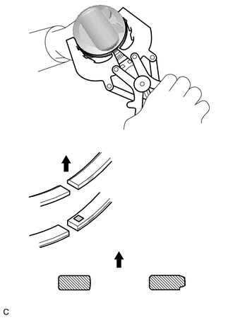
| *a | No. 1 Compression Ring |
| *b | No. 2 Compression Ring |
| *c | Code Mark (2T or A2) |

|
Upward |
Using a piston ring expander, install the No. 1 compression ring and No. 2 compression ring so that the code marks are positioned as shown in the illustration.
- NOTICE:
-
Install the No. 2 compression ring with the code mark (2T or A2) facing upward.
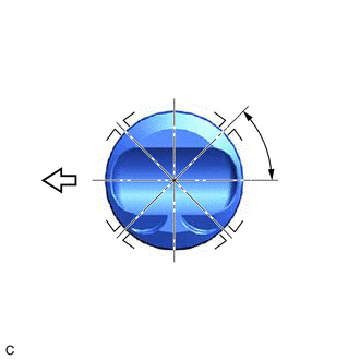
| *1 | No. 1 Compression Ring and Oil Ring Expander |
| *2 | No. 2 Compression Ring |
| *3 | Upper Side Rail |
| *4 | Lower Side Rail |

|
Front of Engine |
Position the piston ring set so that the ring ends are as shown in the illustration.
11711
4.INSTALL CRANKSHAFT BEARING
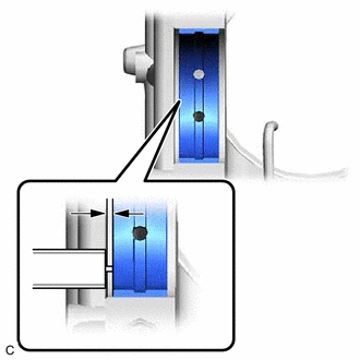
| *a | Vernier Caliper |
Install the 4 upper crankshaft bearings (except the No. 3 journal).
Install the 4 upper crankshaft bearings to the cylinder block sub-assembly.
- NOTICE:
-
Do not apply engine oil to the 4 upper crankshaft bearings or the contact surfaces.
- HINT:
-
Both sides of the oil groove in the cylinder block sub-assembly should be visible through the oil feed holes in the 4 upper crankshaft bearings. The amount visible on each side of the holes should be equal.
Using a vernier caliper, measure the distance between the cylinder block sub-assembly edge and the 4 upper crankshaft bearing edges.
- Difference between (A) and (B):
0.5 to 1.0 mm (0.0197 to 0.0394 in.)
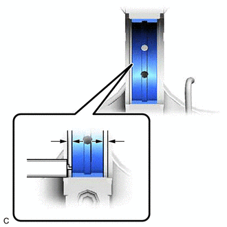
| *a | Vernier Caliper |
Install the upper crankshaft bearing (for the No. 3 journal).
Install the upper crankshaft bearing to the cylinder block sub-assembly.
- NOTICE:
-
Do not apply engine oil to the upper crankshaft bearing or the contact surface.
- HINT:
-
Both sides of the oil groove in the cylinder block sub-assembly should be visible through the oil feed holes in the upper crankshaft bearing. The amount visible on each side of the holes should be equal.
Using a vernier caliper, measure the distance between the cylinder block sub-assembly edge and the upper crankshaft bearing edge.
- Dimension (A):
0.5 mm (0.0197 in.) or less
Install the 5 lower crankshaft bearings.
Install the 5 lower crankshaft bearings to the 5 crankshaft bearing caps.
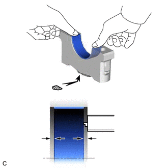
| *a | Mark 1, 2, 3, 4 or 5 |
| *b | Vernier Caliper |
Using a vernier caliper, measure the distance between the 5 crankshaft bearing cap edges and the 5 lower crankshaft bearing edges.
- Difference between (A) and (B):
0.5 mm (0.0197 in.) or less
- NOTICE:
-
Do not apply engine oil to the 5 lower crankshaft bearings or the contact surfaces.
11791
5.INSTALL UPPER CRANKSHAFT THRUST WASHER
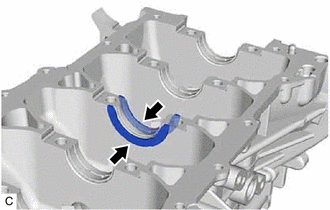
| *a | Oil Groove |
Install the 2 upper crankshaft thrust washers to the No. 3 journal position of the cylinder block sub-assembly with the oil grooves facing outward.
Apply engine oil to the upper crankshaft thrust washers.
13411
6.INSTALL CRANKSHAFT
Apply engine oil to the upper crankshaft bearings and install the crankshaft to the cylinder block sub-assembly.
Apply engine oil to the lower crankshaft bearings.
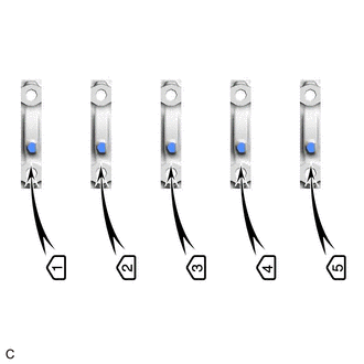
| *a | Front Mark and Number |
Confirm the front marks and numbers, and place the 5 crankshaft bearing caps on the cylinder block sub-assembly.
Apply a light coat of engine oil to the threads and under the heads of the crankshaft bearing cap set bolts.
Temporarily install the 10 crankshaft bearing cap set bolts.
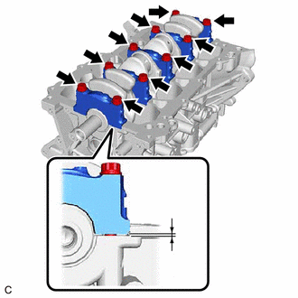
| *a | Less than 5 mm |
Push on the crankshaft bearing caps with your hand until the clearance between the crankshaft bearing caps and cylinder block sub-assembly is less than 5 mm (0.197 in.).
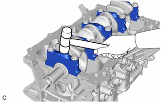
Using a plastic hammer, lightly tap the crankshaft bearing caps to ensure a proper fit.
Install the crankshaft bearing cap set bolts.
- NOTICE:
-
The crankshaft bearing cap set bolts are tightened in 2 progressive steps.
Step 1:
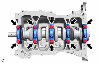
Uniformly tighten the 10 crankshaft bearing cap set bolts in the order shown in the illustration.
- Torque:
- 40 N*m (408 kgf*cm, 30 ft.*lbf)
- HINT:
-
If a crankshaft bearing cap set bolt cannot be tightened to the specified torque, replace it.
Step 2:
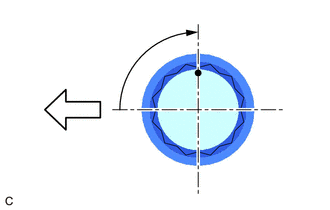
| *a | Paint Mark |
| *b | 90° |
|
|
Front of Engine |
Mark the front of the crankshaft bearing cap set bolts with paint.
Tighten the crankshaft bearing cap set bolts 90° in the order shown in step 1.
Check that the paint marks are now at a 90° angle.
Check that the crankshaft turns smoothly.
Check the crankshaft thrust clearance.
13041
7.INSTALL CONNECTING ROD BEARING
Install the 8 connecting rod bearings to the 4 connecting rods and 4 connecting rod caps.
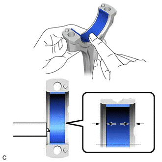
| *a | Vernier Caliper |
Using a vernier caliper, measure the distance between the edges of the connecting rod and connecting rod bearing, and connecting rod cap and connecting rod bearing.
- Difference between (A) and (B):
0.7 mm ( 0.0276 in.) or less
- NOTICE:
-
Do not apply engine oil to the connecting rod bearings or the contact surfaces.
8.INSTALL PISTON SUB-ASSEMBLY WITH CONNECTING ROD
Apply engine oil to the cylinder walls, pistons, and surfaces of the connecting rod bearings.
| *1 | No. 1 Compression Ring and Oil Ring Expander |
| *2 | No. 2 Compression Ring |
| *3 | Upper Side Rail |
| *4 | Lower Side Rail |
|
|
Front of Engine |
Position the piston ring set so that the ring ends are as shown in the illustration.
Confirm that the ends of the oil ring expander are not overlapping and that the upper side rail and lower side rail are securely installed into the groove.
| *a | Press around the circumference | *b | Ring End |
| *c | Correct | *d | Incorrect (Ends of the oil ring expander are overlapping) |
- NOTICE:
- ·
After installing the oil ring expander, upper side rail and lower side rail, press around the circumference with a finger to check that they are securely installed into the groove.
·If the oil ring expander is not securely installed into the groove, check that the ends of the oil ring expander are not overlapping.
·If the ends of the oil ring expander are overlapping, remove the upper side rail and lower side rail and realign the oil ring expander using a screwdriver.
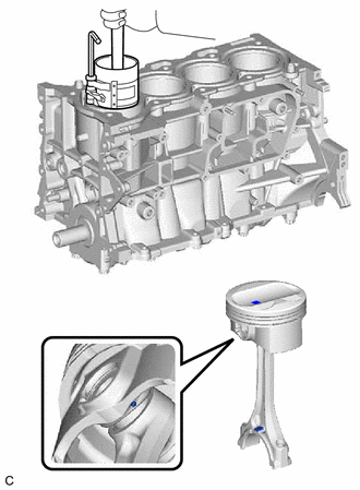
| *a | Front Mark |
Using a piston ring compressor, push the correctly numbered piston with connecting rod into the cylinder with the front marks of each piston sub-assembly with connecting rod facing the front of the engine.
- NOTICE:
- ·
When inserting the piston with connecting rod, do not allow it to make contact with the No. 1 oil nozzle sub-assembly.
·Match each connecting rod cap to the correct connecting rod.
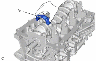
| *a | Front Mark |
Check that the front mark of the connecting rod cap is facing in the correct direction.
Apply a light coat of engine oil to the threads and under the heads of the connecting rod bolts.
Install the 8 connecting rod bolts.
- NOTICE:
-
The connecting rod bolts are tightened in 2 progressive steps.
Step 1:
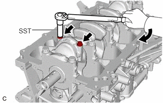
Using SST, alternately tighten the connecting rod bolts in several steps.
- SST
- 09205-16011
- Torque:
- 20 N*m (204 kgf*cm, 15 ft.*lbf)
Step 2:
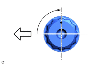
| *a | Paint Mark |
| *b | 90° |
|
|
Front of Engine |
Mark the front of the connecting rod bolts with paint.
Tighten the connecting rod bolts 90° as shown in the illustration.
Check that the crankshaft turns smoothly.
Check the connecting rod thrust clearance.
12211
9.INSTALL NO. 1 VENTILATION CASE
- HINT:
-
There are 2 installation types for the No. 1 ventilation case.
-
Depending on the installation type, the number of bolts, nuts and stud bolts used will vary.
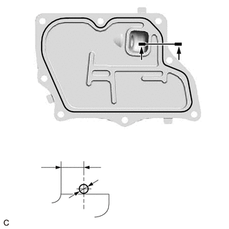
| *a | Seal Packing |
| *b | 2.0 to 3.0 mm (0.0787 to 0.118 in.) |
| *c | 5.0 mm (0.1969 in.) |
Apply seal packing in a continuous line as shown in the illustration.
- Seal Packing:
Toyota Genuine Seal Packing Black, Three Bond 1207B or equivalent
- Application Specification:
Seal Packing Diameter Distance from Inside Edge of Cover to Center of Seal Packing 2.0 to 3.0 mm (0.0787 to 0.118 in.) 5.0 mm (0.1969 in.)
- NOTICE:
- ·
Remove any oil from the contact surfaces.
·Install the No. 1 ventilation case within 3 minutes and tighten the bolts and nuts within 15 minutes of applying seal packing.
·Do not start the engine for at least 2 hours after installation.
Type A:
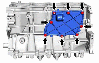
Install the No. 1 ventilation case with the 6 bolts and 2 nuts.
- Torque:
- 10 N*m (102 kgf*cm, 7 ft.*lbf)
Type B:
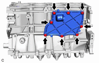
Install the No. 1 ventilation case with the 8 bolts.
- Torque:
- 10 N*m (102 kgf*cm, 7 ft.*lbf)