8ZR-FXE ENGINE MECHANICAL CYLINDER BLOCK REPLACEMENT
PROCEDURE

 1.REPLACE RING PIN
- HINT:
-
It is not necessary to remove the ring pins unless they are being replaced.
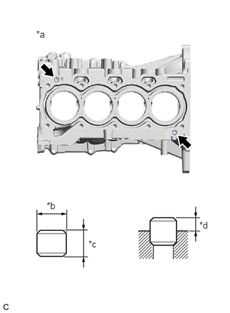
| *a | Top Side |
| *b | Width |
| *c | Height |
| *d | Protrusion Height |
Using a plastic hammer, tap in new ring pins to the cylinder block sub-assembly.
- Standard Ring Pin:
Item Height Width Protrusion Ring Pin 14.3 to 14.7 mm (0.563 to 0.579 in.) 12.9 to 13.0 mm (0.508 to 0.512 in.) 7.5 to 8.5 mm (0.295 to 0.335 in.)
2.REPLACE STUD BOLT
- HINT:
- ·
If a stud bolt is deformed or its threads are damaged, replace it.
·There are 2 installation types for the No. 1 ventilation case.
·This procedure is for type A.
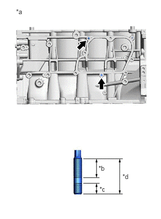
| *a | LH Side |
| *b | 16 mm (0.630 in.) |
| *c | 9 mm (0.354 in.) |
| *d | 27 mm (1.06 in.) |
Using an E6 "TORX" socket wrench, install the stud bolts to the cylinder block sub-assembly as shown in the illustration.
- Torque:
- 5.0 N*m (51 kgf*cm, 44 in.*lbf)
3.REPLACE STRAIGHT PIN
- HINT:
-
It is not necessary to remove the straight pins unless they are being replaced.
Using a plastic hammer, tap in new straight pins to the cylinder block sub-assembly.
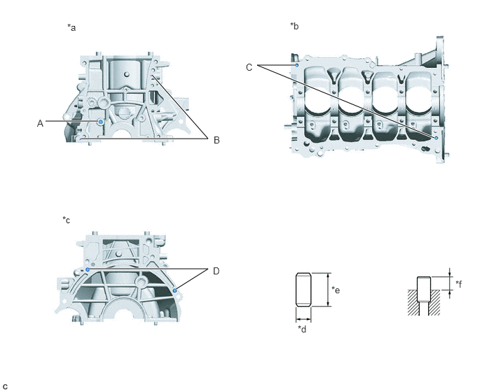
| *a | Front Side | *b | Bottom Side |
| *c | Rear Side | *d | Width |
| *e | Height | *f | Protrusion Height |
- Standard Straight Pin:
Item Height Width Protrusion Pin (A) 36 mm (1.42 in.) 10 mm (0.394 in.) 18.5 to 19.5 mm (0.728 to 0.768 in.) Pin (B) 12 mm (0.472 in.) 4 mm (0.157 in.) 5.0 to 7.0 mm (0.197 to 0.276 in.) Pin (C) 22 mm (0.866 in.) 10 mm (0.394 in.) 8.0 to 10.0 mm (0.315 to 0.394 in.) Pin (D) 18 mm (0.709 in.) 8 mm (0.315 in.) 8.0 to 10.0 mm (0.315 to 0.394 in.)
13201A
4.REPLACE CONNECTING ROD SMALL END BUSH
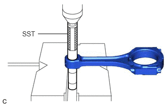
Using SST and a press, press out the connecting rod small end bush.
- SST
- 09222-30010
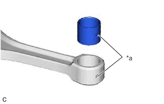
| *a | Oil Hole |
Align the oil holes of a new connecting rod small end bush and the connecting rod.
Using SST and a press, press in the connecting rod small end bush.
- SST
- 09222-30010
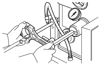
Using a pin hole grinder, hone the connecting rod small end bush to obtain the standard oil clearance between the connecting rod small end bush and piston pin.
- Standard Oil Clearance:
0.005 to 0.011 mm (0.000197 to 0.000433 in.)
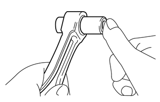
Coat the piston pin with engine oil. Push the piston pin into the connecting rod with your thumb to check that the piston pin fits at normal room temperature.