8ZR-FXE ENGINE MECHANICAL CYLINDER HEAD REPLACEMENT
PROCEDURE

 11155A
1.REPLACE RING PIN
11155A
1.REPLACE RING PIN
- HINT:
-
It is not necessary to remove the ring pins unless they are being replaced.
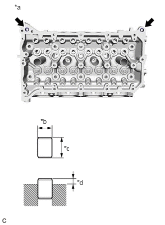
| *a | Top Side |
| *b | Width |
| *c | Height |
| *d | Protrusion Height |
Using a plastic hammer, tap in 2 new ring pins to the cylinder head sub-assembly.
- Standard Ring Pin:
Item Height Width Protrusion Ring pin 11.7 to 12.3 mm (0.461 to 0.484 in.) 12.0 mm (0.472 in.) 6.5 to 7.5 mm (0.256 to 0.295 in.)
2.REPLACE STUD BOLT
- HINT:
-
If a stud bolt is deformed or its threads are damaged, replace it.
Using E7 and E8 "TORX" socket wrenches, install the 9 stud bolts to the cylinder head sub-assembly.
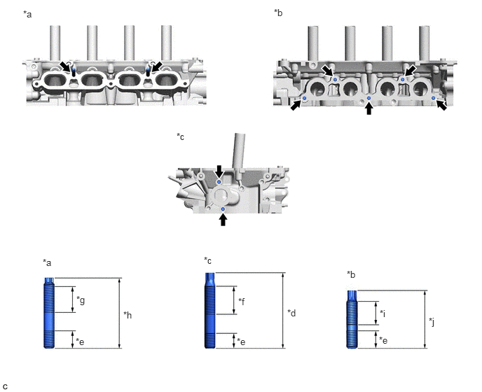
| *a | Intake Manifold Side | *b | Exhaust Manifold Side |
| *c | Cylinder Head Rear Side | *d | 55 mm (2.17 in.) |
| *e | 13 mm (0.512 in.) | *f | 26 mm (1.02 in.) |
| *g | 24 mm (0.945 in.) | *h | 49.5 mm (1.95 in.) |
| *i | 20 mm (0.787 in.) | *j | 42 mm (1.65 in.) |
- Torque:
- 9.5 N*m (97 kgf*cm, 84 in.*lbf)
11122
3.REPLACE INTAKE VALVE GUIDE BUSH
Heat the cylinder head sub-assembly to between 80 and 100°C (176 and 212°F).
Place the cylinder head sub-assembly on wooden blocks.
- CAUTION:
-
Be sure to wear protective gloves.
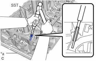
| *a | Wooden Block |
Using SST and a hammer, tap out the intake valve guide bush.
- SST
- 09201-10000 (09201-01050)
09950-70010 (09951-07100)
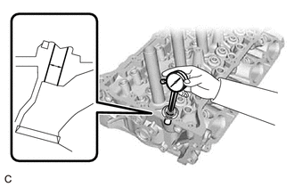
Using a caliper gauge, measure the intake valve guide bush bore diameter of the cylinder head sub-assembly.
- Standard Intake Valve Guide Bush Bore Diameter:
10.285 to 10.306 mm (0.40492 to 0.40575 in.)
- New Guide Bush Selection Chart:
Bush Size Bush Bore Diameter STD 10.333 to 10.344 mm (0.40681 to 0.40724 in.) O/S 0.05 10.383 to 10.394 mm (0.40878 to 0.40921 in.)
- HINT:
- ·
If the intake valve guide bush bore diameter is more than 10.306 mm (0.40575 in.), machine the intake valve guide bush bore to a dimension of 10.335 to 10.356 mm (0.40689 to 0.40772 in.) to install an O/S 0.05 intake valve guide bush.
·If the intake valve guide bush bore diameter of the cylinder head sub-assembly is more than 10.356 mm (0.40772 in.), replace the cylinder head sub-assembly.
Heat the cylinder head sub-assembly to between 80 and 100°C (176 and 212°F).
Place the cylinder head sub-assembly on wooden blocks.
- CAUTION:
-
Be sure to wear protective gloves.
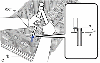
| *a | Protrusion Height |
| *b | Wooden Block |
Using SST and a hammer, tap in a new intake valve guide bush to the specified protrusion height.
- SST
- 09201-10000 (09201-01050)
09950-70010 (09951-07100)
- Standard Protrusion Height:
9.9 to 10.3 mm (0.390 to 0.406 in.)
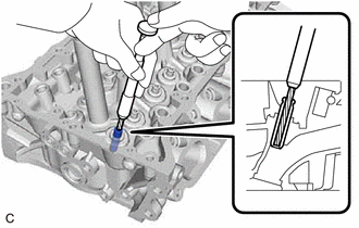
Using a sharp 5.5 mm reamer, ream the intake valve guide bush to obtain the specified oil clearance.
- Standard Oil Clearance:
0.025 to 0.060 mm (0.000984 to 0.00236 in.)
11126
4.REPLACE EXHAUST VALVE GUIDE BUSH
Heat the cylinder head sub-assembly to between 80 and 100°C (176 and 212°F).
Place the cylinder head sub-assembly on wooden blocks.
- CAUTION:
-
Be sure to wear protective gloves.
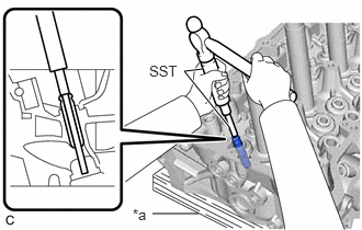
| *a | Wooden Block |
Using SST and a hammer, tap out the exhaust valve guide bush.
- SST
- 09201-10000 (09201-01050)
09950-70010 (09951-07100)
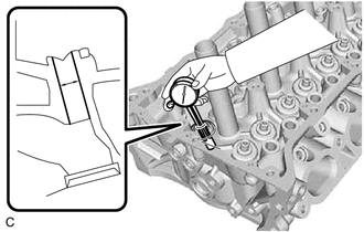
Using a caliper gauge, measure the exhaust valve guide bush bore diameter of the cylinder head sub-assembly.
- Standard Exhaust Valve Guide Bush Bore Diameter:
10.285 to 10.306 mm (0.40492 to 0.40575 in.)
- New Guide Bush Selection Chart:
Bush Size Bush Bore Diameter STD 10.333 to 10.344 mm (0.40681 to 0.40724 in.) O/S 0.05 10.383 to 10.394 mm (0.40878 to 0.40921 in.)
- HINT:
- ·
If the exhaust valve guide bush bore diameter is more than 10.306 mm (0.40575 in.), machine the exhaust valve guide bush bore to a dimension of 10.335 to 10.356 mm (0.40689 to 0.40772 in.) to install an O/S 0.05 exhaust valve guide bush.
·If the exhaust valve guide bush bore diameter of the cylinder head sub-assembly is more than 10.356 mm (0.40772 in.), replace the cylinder head sub-assembly.
Heat the cylinder head sub-assembly to between 80 and 100°C (176 and 212°F).
Place the cylinder head sub-assembly on wooden blocks.
- CAUTION:
-
Be sure to wear protective gloves.
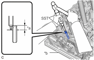
| *a | Protrusion Height |
| *b | Wooden Block |
Using SST and a hammer, tap in a new exhaust valve guide bush to the specified protrusion height.
- SST
- 09201-10000 (09201-01050)
09950-70010 (09951-07100)
- Standard Protrusion Height:
11.15 to 11.55 mm (0.439 to 0.455 in.)
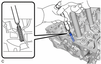
Using a sharp 5.5 mm reamer, ream the exhaust valve guide bush to obtain the specified oil clearance.
- Standard Oil Clearance:
0.030 to 0.065 mm (0.00118 to 0.00256 in.)