NAVIGATION / MULTI INFO DISPLAY NAVIGATION ANTENNA INSPECTION
PROCEDURE

 86860
1.INSPECT NAVIGATION ANTENNA ASSEMBLY (w/o Telematics Transceiver)
86860
1.INSPECT NAVIGATION ANTENNA ASSEMBLY (w/o Telematics Transceiver)
Current consumption check: (GPS)
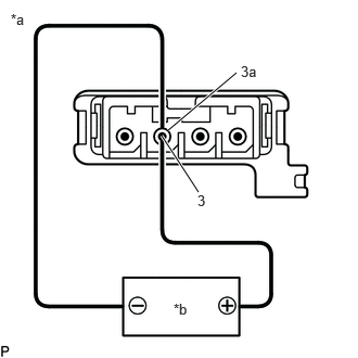
| *a | Component without harness connected
(Navigation Antenna Assembly) |
| *b | Voltage Applied between Terminals |
Measure the current consumption according to the value(s) in the table below.
- Standard Current:
Tester Connection Condition Specified Condition 3 (core) - 3a (shield) 4.2 to 5 V applied between terminals 3 and 3a 10 to 30 mA
- NOTICE:
-
Do not apply a voltage of 6 V or higher between terminals 3 and 3a.
- HINT:
-
If a stable power supply is not available, connect 4 nickel-metal hydride batteries (1.2 V each) or equivalent in series.
If the result is not as specified, replace the navigation antenna assembly.
86860
2.INSPECT NAVIGATION ANTENNA ASSEMBLY (w/ Telematics Transceiver, for ERA-GLONASS)
Current consumption check: (GPS)
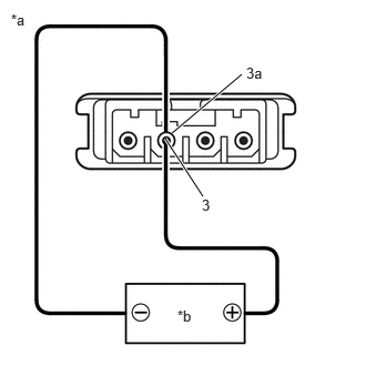
| *a | Component without harness connected
(Navigation Antenna Assembly) |
| *b | Voltage Applied between Terminals |
Measure the current consumption according to the value(s) in the table below.
- Standard Current:
Tester Connection Condition Specified Condition 3 (core) - 3a (shield) 4.2 to 5 V applied between terminals 3 and 3a 10 to 30 mA
- NOTICE:
-
Do not apply a voltage of 6 V or higher between terminals 3 and 3a.
- HINT:
-
If a stable power supply is not available, connect 4 nickel-metal hydride batteries (1.2 V each) or equivalent in series.
If the result is not as specified, replace the navigation antenna assembly.
Resistance check: (Telephone Sub)
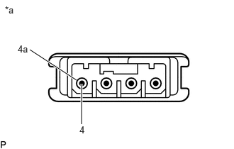
| *a | Component without harness connected
(Navigation Antenna Assembly) |
Measure the resistance according to the value(s) in the table below.
- Standard Resistance:
Tester Connection Condition Specified Condition 4 (core) - 4a (shield) Always 9 to 11 kΩ
If the result is not as specified, replace the navigation antenna assembly.
86860
3.INSPECT NAVIGATION ANTENNA ASSEMBLY (w/ Telematics Transceiver, for Toyota Connected Services)
Current consumption check: (GPS1)
| *a | Component without harness connected
(Navigation Antenna Assembly) |
| *b | Voltage Applied between Terminals |
Measure the current consumption according to the value(s) in the table below.
- Standard Current:
Tester Connection Condition Specified Condition 3 (core) - 3a (shield) 4.2 to 5 V applied between terminals 3 and 3a 10 to 30 mA
- NOTICE:
-
Do not apply a voltage of 6 V or higher between terminals 3 and 3a.
- HINT:
-
If a stable power supply is not available, connect 4 nickel-metal hydride batteries (1.2 V each) or equivalent in series.
If the result is not as specified, replace the navigation antenna assembly.
Current consumption check: (GPS2)
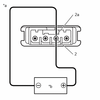
| *a | Component without harness connected
(Navigation Antenna Assembly) |
| *b | Voltage Applied between Terminals |
Measure the current consumption according to the value(s) in the table below.
- Standard Current:
Tester Connection Condition Specified Condition 2 (core) - 2a (shield) 4.2 to 5 V applied between terminals 3 and 3a 10 to 30 mA
- NOTICE:
-
Do not apply a voltage of 6 V or higher between terminals 2 and 2a.
- HINT:
-
If a stable power supply is not available, connect 4 nickel-metal hydride batteries (1.2 V each) or equivalent in series.
If the result is not as specified, replace the navigation antenna assembly.
Resistance check: (Telephone Sub)
| *a | Component without harness connected
(Navigation Antenna Assembly) |
Measure the resistance according to the value(s) in the table below.
- Standard Resistance:
Tester Connection Condition Specified Condition 4 (core) - 4a (shield) Always 9 to 11 kΩ
If the result is not as specified, replace the navigation antenna assembly.