WIPER / WASHER REAR WIPER MOTOR INSTALLATION
PROCEDURE

 85143R
1.INSTALL REAR WIPER MOTOR GROMMET (except Double Swing Out Type)
85143R
1.INSTALL REAR WIPER MOTOR GROMMET (except Double Swing Out Type)
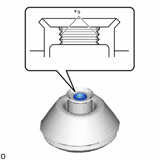
| *a | Rear Wiper Motor Grommet Lip |
Apply MP grease to the entire surface of the rear wiper motor grommet lip.
- HINT:
-
Make sure that the hole does not get clogged with grease and the grooves on the lip are filled with grease.
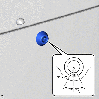
| *a | Matchmark |
Install the rear wiper motor grommet as shown in the illustration.
- Standard:
Area Standard Condition A 20°
- HINT:
-
Check that the matchmark is in the range shown in the illustration.
85143R
2.INSTALL REAR WIPER MOTOR GROMMET (for Double Swing Out Type)
- HINT:
-
Use the same procedure for the RH and LH sides.
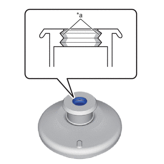
| *a | Rear Wiper Motor Grommet Lip |
Apply MP grease to the entire surface of the rear wiper motor grommet lip.
- HINT:
-
Make sure that the hole does not get clogged with grease and the grooves on the lip are filled with grease.
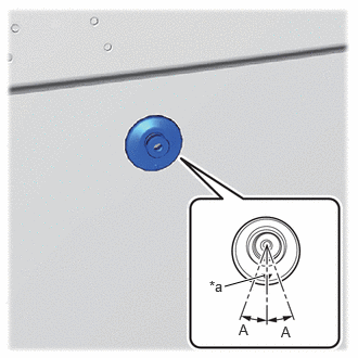
| *a | Matchmark |
Install the rear wiper motor grommet as shown in the illustration.
- Standard:
Area Standard Condition A 20°
- HINT:
-
Check that the matchmark is in the range shown in the illustration.
85110R
3.INSTALL REAR WIPER MOTOR ASSEMBLY (except Double Swing Out Type)


|
Bolt |

|
Connector |
Install the rear wiper motor assembly with the 3 bolts.
- Torque:
- 5.5 N*m (56 kgf*cm, 49 in.*lbf)
Attach the clamp and connect the connector.
- NOTICE:
-
Do not reuse the rear wiper motor assembly which has been subjected to an impact or dropped.
85110R
4.INSTALL REAR WIPER MOTOR ASSEMBLY (for Double Swing Out Type)
Install the rear wiper motor assembly with the 3 bolts.
- Torque:
- 5.5 N*m (56 kgf*cm, 49 in.*lbf)
Attach the clamp and connect the connector.
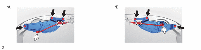
| *A | for RH Side | *B | for LH Side |
|
|
Bolt |
|
Connector |
- NOTICE:
-
Do not reuse the rear wiper motor assembly which has been subjected to an impact or dropped.
5.INSTALL REAR WIPER ARM AND BLADE ASSEMBLY (except Double Swing Out Type)
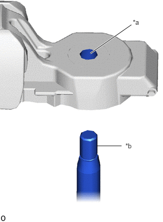
| *a | Rear Wiper Arm Serrations |
| *b | Rear Wiper Motor Assembly Pivot Serrations |
When reusing the rear wiper arm and blade assembly:
Clean the rear wiper arm serrations.
- NOTICE:
-
Do not grind the rear wiper arm serrations.
When reusing the rear wiper motor assembly:
Using a wire brush, clean the rear wiper motor assembly pivot serrations.
- NOTICE:
-
Do not grind the rear wiper motor assembly pivot serrations.
Turn the ignition switch to ON.
Operate the rear wiper motor assembly and stop at the automatic stop (park) position.
Turn the ignition switch off.
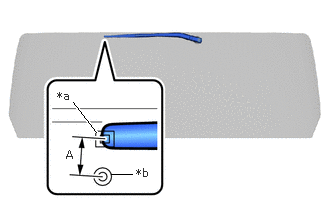
| *a | Matchmark |
| *b | Stopped Position Marking |
Align the end of the rear wiper arm and blade assembly with the center of the assembly marking and install the rear wiper arm and blade assembly with the nut as shown in the illustration.
- Torque:
- 5.5 N*m (56 kgf*cm, 49 in.*lbf)
- Standard:
Area Standard Condition A 17 mm (0.669 in.)
- HINT:
- ·
After the rear wiper motor assembly is stopped, check the automatic stop position after lifting the wiper blade 2 times.
·Hold the rear wiper arm by hand while tightening the nut.
- OK:
Stop the rear wiper motor assembly so that it is between the matchmark and the stopped position marking as shown in the illustration.
Turn the ignition switch to ON.
Operate the rear wiper while spraying washer fluid onto the back door glass. Make sure that the rear wiper functions properly and the wiper does not come into contact with the vehicle body.
Turn the ignition switch off.
Raise the rear wiper arm 2 times and check that the tip of the rear wiper blade is within the range shown in the illustration.
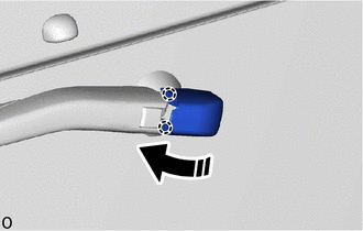

|
Install in this Direction |
Lower the rear wiper arm head cap in the direction indicated by the arrow shown in the illustration and attach the claw.
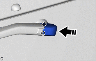
|
|
Install in this Direction |
Slide the rear wiper arm head cap as shown in the illustration to attach the claw.
6.INSTALL WIPER ARM AND BLADE ASSEMBLY LH (for Double Swing Out Type)
| *a | Rear Wiper Arm Serrations |
| *b | Rear Wiper Motor Assembly Pivot Serrations |
When reusing the rear wiper arm and blade assembly:
Clean the rear wiper arm serrations.
- NOTICE:
-
Do not grind the rear wiper arm serrations.
When reusing the rear wiper motor assembly:
Using a wire brush, clean the rear wiper motor assembly pivot serrations.
- NOTICE:
-
Do not grind the rear wiper motor assembly pivot serrations.
Turn the ignition switch to ON.
Operate the rear wiper motor assembly and stop at the automatic stop (park) position.
Turn the ignition switch off.
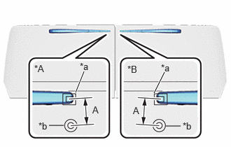
| *A | for LH Side |
| *B | for RH Side |
| *a | Matchmark |
| *b | Stopped Position Marking |
Align the end of the rear wiper arm and blade assembly with the center of the assembly marking and install the rear wiper arm and blade assembly with the nut as shown in the illustration.
- Torque:
- 5.5 N*m (56 kgf*cm, 49 in.*lbf)
- Standard:
Area Standard Condition A 16.5 mm (0.650 in.)
- HINT:
- ·
After the rear wiper motor assembly is stopped, check the automatic stop position after lifting the wiper blade 2 times.
·Hold the rear wiper arm by hand while tightening the nut.
- OK:
Stop the rear wiper motor assembly so that it is between the matchmark and the stopped position marking as shown in the illustration.
Turn the ignition switch to ON.
Operate the rear wiper while spraying washer fluid onto the back door glass. Make sure that the rear wiper functions properly and the wiper does not come into contact with the vehicle body.
Turn the ignition switch off.
Raise the rear wiper arm 2 times and check that the tip of the rear wiper blade is within the range shown in the illustration.
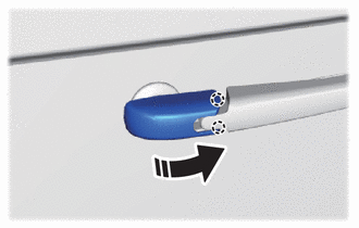
|
|
Install in this Direction |
Lower the rear wiper arm head cap in the direction indicated by the arrow shown in the illustration and attach the claw.
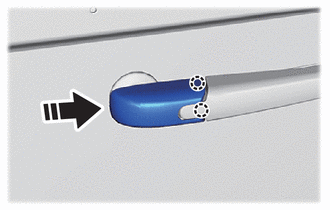
|
|
Install in this Direction |
Slide the rear wiper arm head cap as shown in the illustration to attach the claw.
7.INSTALL WIPER ARM AND BLADE ASSEMBLY RH (for Double Swing Out Type)
- HINT:
-
Use the same procedure described for the LH side.
67760A
8.INSTALL BACK DOOR UPPER TRIM BOARD ASSEMBLY (except Wagon, for Regular)
67760A
9.INSTALL BACK DOOR UPPER TRIM BOARD ASSEMBLY (except Wagon, for Large)
67760A
10.INSTALL BACK DOOR UPPER TRIM BOARD ASSEMBLY (for Wagon)
67760A
11.INSTALL BACK DOOR UPPER TRIM BOARD ASSEMBLY (for Double Swing Out Type)
67938A
12.INSTALL BACK DOOR SIDE GARNISH LH (for Wagon)
67937B
13.INSTALL BACK DOOR SIDE GARNISH RH (for Wagon)
- HINT:
-
Use the same procedure described for the LH side.