EXTERIOR PANELS / TRIM REAR BUMPER(except Wagon) DISASSEMBLY
PROCEDURE

 89342
1.REMOVE REAR CORNER ULTRASONIC SENSOR (w/ TOYOTA Parking Assist-sensor System)
89342
1.REMOVE REAR CORNER ULTRASONIC SENSOR (w/ TOYOTA Parking Assist-sensor System)
89342A
2.REMOVE REAR CENTER ULTRASONIC SENSOR (w/ TOYOTA Parking Assist-sensor System)
89348D
3.REMOVE ULTRASONIC SENSOR CLIP (w/ TOYOTA Parking Assist-sensor System)
89C48A
4.REMOVE REAR CORNER ULTRASONIC SENSOR RETAINER (w/ TOYOTA Parking Assist-sensor System)
89C48B
5.REMOVE REAR CENTER ULTRASONIC SENSOR RETAINER (w/ TOYOTA Parking Assist-sensor System)
52164A
6.REMOVE REAR BUMPER PLATE LH (for Double Swing Out Type, w/ Blind Spot Monitor System)
- HINT:
-
When removing the rear bumper plate LH, if the double-sided tape is difficult to remove, heat the adhesive of the rear bumper plate LH and rear bumper cover using a heat light.
- Standard Value:
Part Temperature Rear Bumper Cover 20 to 30°C (68 to 86°F) Rear Bumper Plate LH 20 to 30°C (68 to 86°F)
- CAUTION:
-
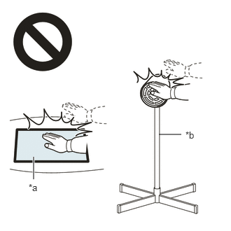 2.365,2 2.698,2 false 0.5,2.333 0.5,2.667 true 0.427,2.708 0.74,2.865 0.313,0.156 10 false *a 2.76,1.927 3.073,2.083 0.313,0.156 10 false *b
*a Heated Part *b Heat Light
- ·
Do not touch the heat light and heated parts.
·Touching the heat light may result in burns.
·Touching heated parts for a long time may result in burns.
- NOTICE:
-
Do not heat the rear bumper plate LH excessively.
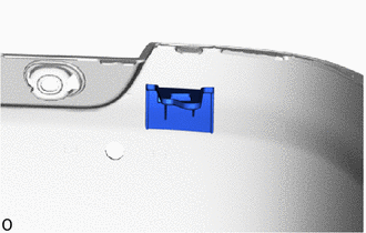
Remove the rear bumper plate LH.
52163A
7.REMOVE REAR BUMPER PLATE RH (for Double Swing Out Type, w/ Blind Spot Monitor System)
- HINT:
-
Use the same procedure for the RH and LH sides.
82182
8.REMOVE NO. 2 LUGGAGE ROOM WIRE (w/ TOYOTA Parking Assist-sensor System)
Detach the wire harness clamp and remove the No. 2 luggage room wire.
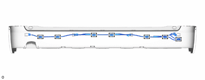
89348Y
9.REMOVE REAR ULTRASONIC SENSOR CLIP (w/ TOYOTA Parking Assist-sensor System)
- HINT:
-
When removing the rear ultrasonic sensor clip, if the double-sided tape is difficult to remove, heat the adhesive of the rear ultrasonic sensor clip and rear bumper cover using a heat light.
- Standard Value:
Part Temperature Rear Bumper Cover 20 to 30°C (68 to 86°F) Rear Ultrasonic Sensor Clip 20 to 30°C (68 to 86°F)
- CAUTION:
-
2.365,2 2.698,2 false 0.5,2.333 0.5,2.667 true 0.427,2.708 0.74,2.865 0.313,0.156 10 false *a 2.76,1.927 3.073,2.083 0.313,0.156 10 false *b
*a Heated Part *b Heat Light
- ·
Do not touch the heat light and heated parts.
·Touching the heat light may result in burns.
·Touching heated parts for a long time may result in burns.
- NOTICE:
-
Do not heat the rear ultrasonic sensor clip excessively.
Remove the 7 rear ultrasonic sensor clips.
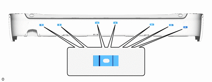
52169C
10.REMOVE REAR BUMPER LOWER COVER (w/ Rear Bumper Lower Cover)
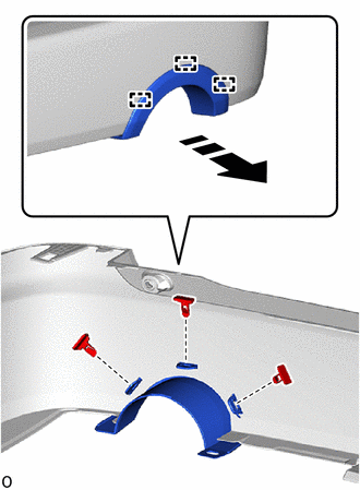

|
Remove in this Direction |
Remove the 3 outside moulding retainers.
Detach the guide and remove the rear bumper lower cover.
52016A
11.REMOVE REAR BUMPER ARM SUB-ASSEMBLY LH (w/ Rear Bumper Arm)
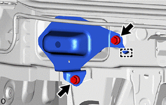
Remove the 2 bolts.
Detach the hook and remove the rear bumper arm sub-assembly LH.
58385A
12.REMOVE REAR BUMPER COVER BRACKET (w/ Rear Bumper Lower Cover)
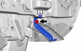
Remove the bolt.
Detach the hook and remove the rear bumper cover bracket.
52015A
13.REMOVE REAR BUMPER ARM SUB-ASSEMBLY RH (w/ Rear Bumper Arm)
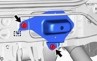
| *A | w/o Rear Bumper Lower Cover |
w/ Rear Bumper Lower Cover:
Remove the bolt.
w/o Rear Bumper Lower Cover:
Remove the 2 bolts.
Detach the hook and remove the rear bumper arm sub-assembly RH.
76626D
14.REMOVE REAR QUARTER PANEL MUDGUARD LH (w/ Mudguard)
76625D
15.REMOVE REAR QUARTER PANEL MUDGUARD RH (w/ Mudguard)
- HINT:
-
Use the same procedure for the RH and LH sides.
61682A
16.REMOVE REAR WHEEL OPENING EXTENSION LH
w/ Rear Wheel House Liner:
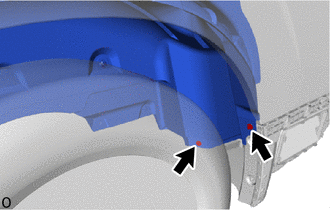
Remove the 2 screws.
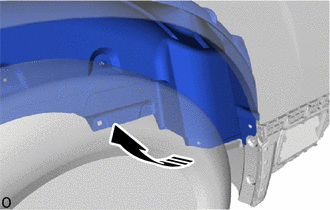
|
|
Move in this Direction |
Fold back the rear wheel house liner LH in the direction indicated by the arrow shown in the illustration.
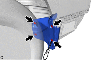
Using a screwdriver, remove the 4 grommets and rear wheel opening extension LH.
61681C
17.REMOVE REAR WHEEL OPENING EXTENSION RH
- HINT:
-
Use the same procedure for the RH and LH sides.
52156A
18.REMOVE REAR BUMPER SIDE SUPPORT LH
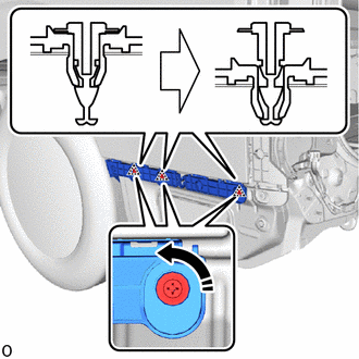
| *a | 90° |
|
|
Move in this Direction |
Using a screwdriver, turn the clip 90° and detach the clip as shown in the illustration.
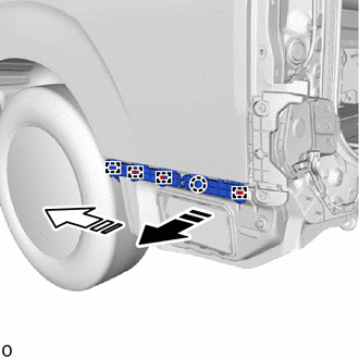
|
|
Remove in this Direction (1) |

|
Remove in this Direction (2) |
Detach the guide and claw and remove the rear bumper side support LH as shown in the illustration.
52155A
19.REMOVE REAR BUMPER SIDE SUPPORT RH
- HINT:
-
Use the same procedure for the RH and LH sides.
52158C
20.REMOVE REAR BUMPER NO. 2 SIDE SUPPORT LH
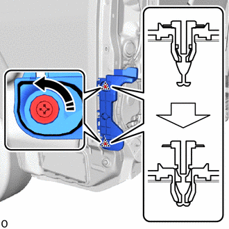
| *a | 90° |
|
|
Move in this Direction |
Using a screwdriver, turn the clip 90° and detach the clip as shown in the illustration.
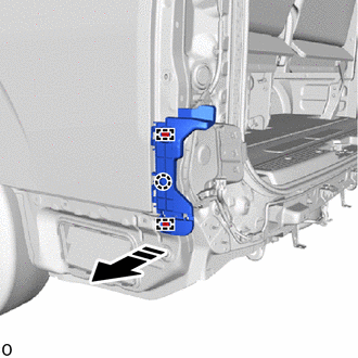
|
|
Remove in this Direction |
Detach the guide and claw and remove the rear bumper No. 2 side support LH as shown in the illustration.
52157A
21.REMOVE REAR BUMPER NO. 2 SIDE SUPPORT RH
- HINT:
-
Use the same procedure for the RH and LH sides.