LIGHTING (INT) BACK DOOR COURTESY SWITCH(for Double Swing Out Type) INSPECTION
PROCEDURE

 69350
1.INSPECT BACK DOOR LOCK ASSEMBLY
69350
1.INSPECT BACK DOOR LOCK ASSEMBLY
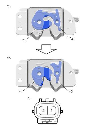
| *1 | Back Door Lock Hook |
| *2 | Back Door Lock Ratchet |
| *a | Closed (Locked) |
| *b | Opened (Unlocked) |
| *c | Component without harness connected
(Back Door Lock Assembly) |
Check the operation of the back door courtesy switch.
Measure the resistance according to the value(s) in the table below.
- Standard Resistance:
Tester Connection Condition Specified Condition 1 - 2 Back door closed (Locked) 10 kΩ or higher 1 - 2 Back door opened (Unlocked) Below 1 Ω
If the result is not as specified, replace the back door lock assembly.
69690
2.INSPECT BACK DOOR REMOTE CONTROL ASSEMBLY
Check the operation of the back door remote control assembly.

| *a | Direction of Lock Operation | *b | Direction of Unlock Operation |
| *c | Component without harness connected
(Back Door Remote Control Assembly) |
- | - |
Apply battery voltage and check the operation of the closer motor.
- OK:
Battery Connection Specified Condition Battery positive (+) → Terminal 3 (ACT+)
Battery negative (-) → Terminal 2 (ACT-)Lock operation Battery positive (+) → Terminal 2 (ACT-)
Battery negative (-) → Terminal 3 (ACT+)Unlock operation
If the result is not as specified, replace the back door remote control assembly.
Check the resistance of the back door remote control assembly (w/ Back Door Control Switch Assembly).
Measure the resistance according to the value(s) in the table below.
- Standard Resistance:
Tester Connection Condition Specified Condition 1 (S) - 4 (E) Lock 10 kΩ or higher 1 (S) - 4 (E) Unlock Below 1 Ω
If the result is not as specified, replace the back door remote control assembly.