TELEMATICS TELEMATICS SYSTEM(for Toyota Connected Services) SYSTEM DESCRIPTION
DESCRIPTION
Toyota Connected Services performs ACN (Automatic Collision Notification), SOS (manual emergency calling) and SVT (Stolen Vehicle Tracking), by audio and data communications between the vehicle and call center through a cellular phone network. As shown in the illustration, when a collision is detected, the vehicle sends its location calculated based on GPS signals and the identification code of the telematics transceiver to a call center. After the necessary information has been gathered, the call center will relay this information to emergency services.
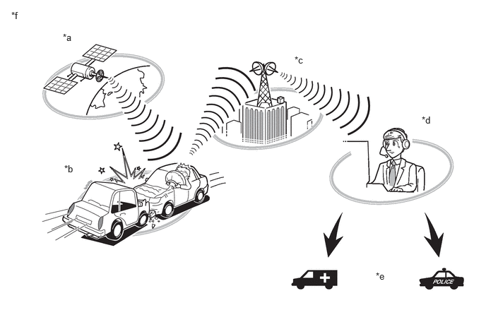
| *a | GPS Satellite | *b | Airbag Deployment |
| *c | Carrier Network | *d | Call Center |
| *e | Emergency Vehicle | *f | The illustrations shown are examples only. The illustrations may differ from the actual service. |
SYSTEM FUNCTION
SOS emergency call
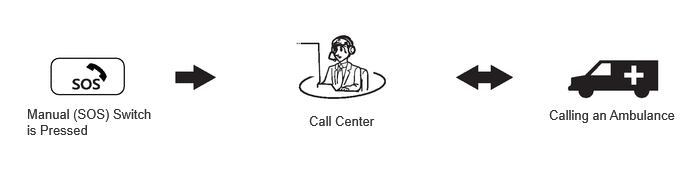
After pressing the manual (SOS) switch, the occupant can talk to an operator from the call center to seek assistance.
ACN (Automatic Collision Notification)
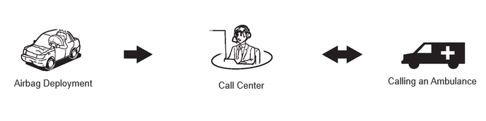
When an airbag is deployed, the vehicle connects to the call center automatically and reports the vehicle location and vehicle information by data communication. The operator will connect to the vehicle and communicate with the occupant. Even if the occupant does not answer, the operator can notify emergency services.
SVT (Stolen Vehicle Tracking)
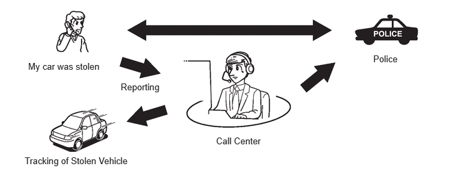
After the vehicle has been reported stolen to the police, the customer can contact the call center to begin the stolen vehicle locator process. The operator locates this vehicle by GPS and provides information to the police.
FUNCTION OF MAIN COMPONENTS
| Component | Function | ||
|---|---|---|---|
|
*: for 12 Speakers |
|||
| Map Light Assembly
·
Manual (SOS) Switch |
When the manual (SOS) switch is pressed, a switch signal is sent to the telematics transceiver. (When a manual emergency call is performed.) | ||
| LED Indicator Light | Green | ·
Illuminates when the system is operating normally. ·
Blinks during an emergency call. ·
Turns off when the system is malfunctioning.
|
|
| Red | ·
Turns off when the system is operating normally. ·
Illuminates when an emergency call is made while the system is still malfunctioning. ·
Illuminates in diagnostic mode to indicate a DTC. ·
Illuminates in diagnostic mode to indicate a specific vehicle history (RoB).
|
||
| Map Light Assembly
·
Telephone Microphone Assembly |
When an emergency call is made: Sends the microphone voice signal to the telematics transceiver. | ||
| Navigation Antenna Assembly | ·
Transmits signals from the telematics transceiver and receives signals from the communication network. (Connect as main) ·
Receives GPS satellite signals and sends them to the telematics transceiver. |
||
| No. 2 Amplifier Antenna Assembly | Receives signals from the communication network. (Connect as sub) | ||
| Telematics Transceiver | ·
Uses the No. 2 amplifier antenna assembly to send and receive data and voice signals used for emergency calls via a communication network. -
When an emergency call is made: Sends the received voice signal to the vehicle speakers. -
When an emergency call is made: Receives the sent voice signal from the telephone microphone assembly. -
When an emergency call is made: Sends a mute signal to the stereo component amplifier assembly. (Mute function becomes active during the call.) -
When an emergency call is made: Sends vehicle location information to the call center. -
When a warning occurs, the telematics transceiver receives a warning ON signal from the combination meter assembly via CAN communication and sends it to the service center. |
||
| Mobilephone Battery | ·
When an automatic emergency call is performed, the mobilephone battery provides power to the telematics transceiver. ·
When a manual emergency call is made, the mobilephone battery is not used as the power source. |
||
| Stereo Component Amplifier Assembly* | Receives the received voice signal sent from the radio and display receiver assembly as a sound signal and outputs it as sound from the front No. 2 speaker assembly LH via the telematics transceiver. (When the operator service is used.) | ||
| Airbag Sensor Assembly | Sends an activation signal to the telematics transceiver when airbags deploy. (An automatic emergency call is made.) | ||
| Combination Meter Assembly | Sends a warning signal to the telematics transceiver via CAN communication when a warning occurs. | ||
MAYDAY ID OUTLINE
The telematics transceiver functions as the emergency call service device to perform emergency calls.
The telematics transceiver has serial numbers (IMEI, ICCID) which can be used to identify the individual device when servicing.
The IMEI is printed on the label attached to the telematics transceiver.
COMMUNICATION SYSTEM
CAN Communication Outline
The telematics system uses CAN communication between the telematics transceiver and ECUs.
DIAGNOSTIC FUNCTION OUTLINE
The telematics system has a diagnostic function (the result will be displayed on the GTS).