POWER ASSIST SYSTEMS POWER STEERING SYSTEM(w/ Variable Flow Control Solenoid Valve) C15F014 VFC Solenoid Circuit Circuit Short to Ground or Open
DESCRIPTION
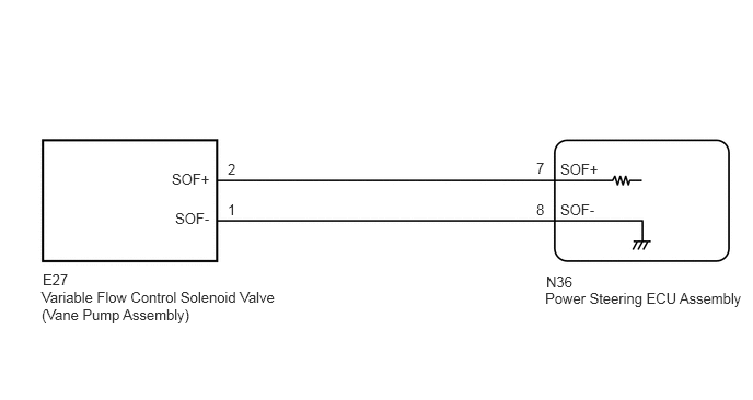
This circuit supplies electric power to the variable flow control solenoid valve (vane pump assembly).
The power steering ECU assembly controls the output current to the variable flow control solenoid valve (vane pump assembly) in accordance with the steering angle signal, steering sensor zero point memory, vehicle speed signal and engine speed signal, adjusting the amount of power steering assist.
| DTC No. | Detection Item | DTC Detection Condition | Trouble Area |
|---|---|---|---|
| C15F014 | VFC Solenoid Circuit Circuit Short to Ground or Open | A short or open in the solenoid valve circuit | ·
Harness or connector ·
Vane pump assembly ·
Power steering ECU assembly |
| Vehicle Condition | |||
|---|---|---|---|
| Pattern 1 | Pattern 2 | ||
| Diagnosis Condition | - | - | - |
| Malfunction Status | A short in the solenoid valve circuit | ○ | - |
| An open in the solenoid valve circuit | - | ○ | |
| Detection Time | - | - | |
| Number of Trips | 1 trip | 1 trip | |
WIRING DIAGRAM
PROCEDURE
Turn the ignition switch off.
Connect the GTS to the DLC3.
Turn the ignition switch to ON.
Turn the GTS on.
Enter the following menus: Chassis / PPS / Data List.
- Chassis > PPS > Data List
-
Tester Display Measurement Item Range Normal Condition Diagnostic Note Solenoid Actual Current (PPS) Solenoid Current Min.: 0 mA
Max.: 1000 mA200 to 950 mA: The engine is running and the steering wheel is being turned -
- OK:
The normal condition value is displayed on the GTS.
- Result:
Proceed to OK NG
OK
NG
Disconnect the N36 power steering ECU assembly connector.
Disconnect the E27 variable flow control solenoid valve (vane pump assembly) connector.
Measure the resistance according to the value(s) in the table below.
- Standard Resistance:
Tester Connection Condition Specified Condition N36-7 (SOF+) - E27-2 (SOF+) Always Below 1 Ω N36-8 (SOF-) - E27-1 (SOF-) N36-7 (SOF+) - Body ground Always 10 kΩ or higher N36-8 (SOF-) - Body ground
- Result:
Proceed to OK NG
OK
NG
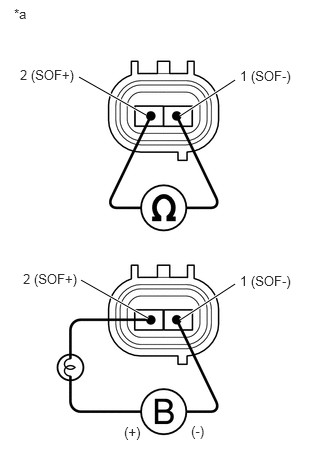
Disconnect the E27 variable flow control solenoid valve (vane pump assembly) connector.
| *a | Component without harness connected
(Variable Flow Control Solenoid Valve (Vane Pump Assembly)) |
Measure the resistance according to the value(s) in the table below.
- Standard Resistance:
Tester Connection Condition Specified Condition 1 (SOF-) - 2 (SOF+) 20°C (68°F) 6.7 to 7.3 Ω
Connect the positive (+) lead of the battery with a 21 W bulb to terminal 2 (SOF+) and the negative (-) lead to terminal 1 (SOF-) of the solenoid valve connector. Then check that the valve moves and makes an operating noise.
- OK:
Valve moves and makes an operating noise.
- Result:
Proceed to OK NG
OK
NG