AC60E AUTOMATIC TRANSMISSION / TRANSAXLE AUTOMATIC TRANSMISSION UNIT(for 7GR-FKS) REASSEMBLY
PROCEDURE

 1. BEARING POSITION
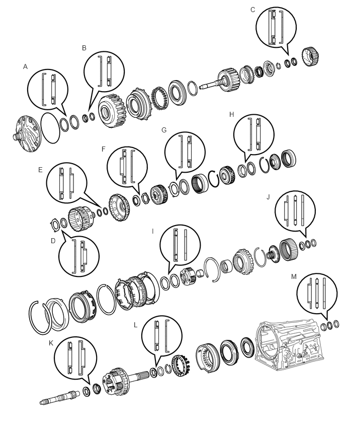
- Bearing and Race Diameter:
Mark Front Race Diameter Inside / Outside (mm (in.)) Thrust Bearing Diameter Inside / Outside (mm (in.)) Rear Race Diameter Inside / Outside (mm (in.)) A 74.2 (2.921) / 87.74 (3.454) 71.9 (2.831) / 85.6 (3.370) - B 40.0 (1.575) / 52.8 (2.079) 34.6 (1.362) / 52.0 (2.047) - C 22.6 (0.890) / 44.8 (1.764) 21.3 (0.839) / 41.1 (1.618) - D 38.4 (1.512) / 56.5 (2.224) 33.3 (1.311) / 56.6 (2.228) - E - 40.83 (1.607) / 52.8 (2.079) 39.6 (1.559) / 52.8 (2.079) F - 37.1 (1.461) / 61.2 (2.409) 44.0 (1.732) / 62.8 (2.472) G 65.8 (2.591) / 86.3 (3.398) 63.3 (2.492) / 78.8 (3.102) - H 66.3 (2.610) / 78.9 (3.106) 63.3 (2.492) / 78.8 (3.102) - I - 55.7 (2.193) / 76.4 (3.008) 53.7 (2.114) / 74.0 (2.913) J 33.4 (1.315) / 49.0 (1.929) 32.1 (1.264) / 49.35 (1.943) 32.1 (1.264) / 49.0 (1.929) K - 21.0 (0.827) / 41.5 (1.634) 23.13 (0.911) / 41.5 (1.634) L - 43.55 (1.715) / 61.0 (2.402) 47.1 (1.854) / 67.1 (2.642) M 37.0 (1.457) / 51.2 (2.016) 36.1 (1.421) / 52.5 (2.067) 36.1 (1.421) / 51.0 (2.008)
35639B
2.INSTALL BRAKE PLATE STOPPER SPRING
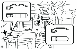
Install the 2 brake plate stopper springs to the automatic transmission case sub-assembly.
- NOTICE:
-
The shapes of the parts are different. Refer to the illustration when installing the parts.
35629A
3.INSTALL NO. 4 BRAKE PISTON
Coat 2 new O-rings with ATF, and install them to the brake reaction sleeve.
Coat 2 new O-rings with ATF, and install them to the No. 4 brake piston.
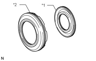
| *1 | No. 4 Brake Piston |
| *2 | Brake Reaction Sleeve |
Install the No. 4 brake piston to the brake reaction sleeve.
- NOTICE:
-
Be careful not to damage the O-rings.
35626
4.INSTALL BRAKE REACTION SLEEVE
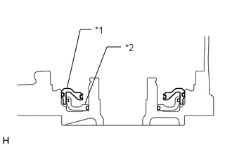
| *1 | Brake Reaction Sleeve |
| *2 | No. 4 Brake Piston |
With the No. 4 brake piston underneath (the rear side), install the brake reaction sleeve and No. 4 brake piston to the automatic transmission case sub-assembly.
- NOTICE:
-
Be careful not to damage the O-rings.
35623H
5.INSTALL 1ST AND REVERSE BRAKE PISTON
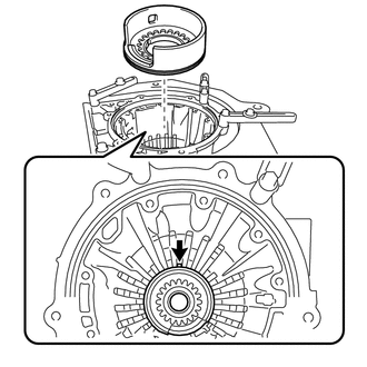
Coat a new O-ring with ATF, and install it to the 1st and reverse brake piston.
Install the 1st and reverse brake piston to the automatic transmission case sub-assembly while making sure that the protrusion of the 1st and reverse brake piston is positioned as shown in the illustration.
- NOTICE:
-
Be careful not to damage the O-ring.
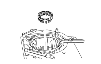
Install the 1st and reverse brake return spring sub-assembly to the automatic transmission case sub-assembly.
Place the 1st and reverse brake return spring sub-assembly onto the 1st and reverse brake piston.
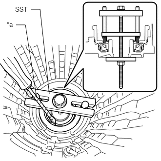
| *a | Protective Tape |
Place SST on the 1st and reverse brake return spring sub-assembly, and compress the 1st and reverse brake return spring sub-assembly.
- SST
- 09380-60012 (09381-06030, 09381-05040, 09381-06040, 09381-06080, 09381-05050, 09381-06120, 09381-06130, 09381-06140)
Using a screwdriver, install the snap ring to the automatic transmission case sub-assembly.
- NOTICE:
-
Be careful not to damage the 1st and reverse brake return spring sub-assembly and automatic transmission case sub-assembly.
- HINT:
-
Tape the screwdriver tip before use.
35760
6.INSTALL REAR PLANETARY GEAR ASSEMBLY
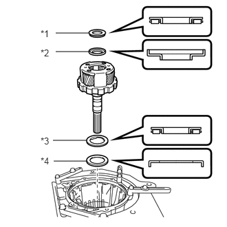
| *1 | Thrust Needle Roller Bearing K |
| *2 | Thrust Bearing Race K |
| *3 | Thrust Needle Roller Bearing L |
| *4 | Thrust Bearing Race L |
Coat the thrust bearing race with ATF and install it to the automatic transmission case sub-assembly.
- Thrust Needle Roller Bearing and Thrust Bearing Race Diameter:
Item Inside (mm (in.)) Outside (mm (in.)) Thrust Needle Roller Bearing K 21.0 (0.827) 41.5 (1.634) Thrust Bearing Race K 23.13 (0.911) 41.5 (1.634) Thrust Needle Roller Bearing L 43.55 (1.715) 61.0 (2.402) Thrust Bearing Race L 47.1 (1.854) 67.1 (2.642)
- NOTICE:
-
Be sure to install the thrust needle roller bearing and thrust bearing race in the correct direction.
Coat the 2 thrust needle roller bearings and thrust bearing races with ATF and install them to the rear planetary gear assembly.
Install the rear planetary gear assembly to the automatic transmission case sub-assembly.
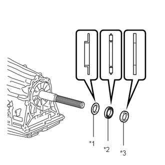
| *1 | Thrust Bearing Race M (Front Race) |
| *2 | Needle Roller Bearing M |
| *3 | Thrust Bearing Race M (Rear Race) |
Coat the thrust needle roller bearing and 2 thrust bearing races with ATF and install them to the output shaft of the rear planetary gear assembly.
- Bearing and Race Diameter:
Item Inside (mm (in.)) Outside (mm (in.)) Thrust Bearing Race M
(Front Race)37.0 (1.457) 51.2 (2.016) Thrust Needle Roller Bearing M 36.1 (1.421) 52.5 (2.067) Thrust Bearing Race M
(Rear Race)36.1 (1.421) 51.0 (2.008)
- NOTICE:
-
Be sure to install the thrust needle roller bearing and thrust bearing race in the correct direction.
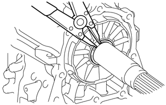
Using a snap ring expander, install the snap ring.
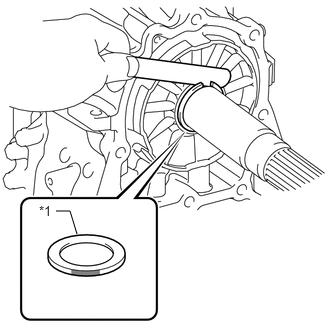
| *1 | Thrust Bearing Race M (Rear Race) |

|
Mark Area |
Using a feeler gauge, measure the clearance between the snap ring and thrust bearing race.
- Standard Clearance:
0.02 to 0.12 mm (0.000788 to 0.00472 in.)
If the clearance is outside the standard range, select another thrust bearing race that brings the clearance within the standard range.
- HINT:
-
There are 12 different thicknesses for the thrust bearing race.
| Part No. | Mark | Thickness |
|---|---|---|
| 35789-35060 | 
|
3.80 mm (0.150 in.) |
| 35789-50070 | 
|
3.85 mm (0.152 in.) |
| 35789-35070 | 
|
3.90 mm (0.154 in.) |
| 35789-50080 | 
|
3.95 mm (0.156 in.) |
| 35789-35080 | 
|
4.00 mm (0.157 in.) |
| 35789-50090 | 
|
4.05 mm (0.159 in.) |
| 35789-35090 | 
|
4.10 mm (0.161 in.) |
| 35789-50100 | 
|
4.15 mm (0.163 in.) |
| 35789-35100 | 
|
4.20 mm (0.165 in.) |
| 35789-50110 | 
|
4.25 mm (0.167 in.) |
| 35789-50120 | 
|
4.30 mm (0.169 in.) |
| 35789-50130 | 
|
4.35 mm (0.171 in.) |
35684
7.INSTALL NO. 4 BRAKE DISC
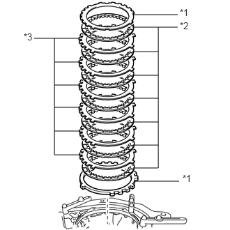
| *1 | No. 4 Brake Flange |
| *2 | No. 4 Brake Disc |
| *3 | No. 4 Brake Plate |
Install the 2 No. 4 brake flanges, 7 No. 4 brake discs and 6 No. 4 brake plates to the automatic transmission case sub-assembly.
- NOTICE:
- ·
Make sure that the No. 4 brake discs, No. 4 brake plates and No. 4 brake flanges are installed in the correct order.
·Install the thicker No. 4 brake flange first, and then install the thinner one.
35713
8.INSTALL INTERMEDIATE SHAFT
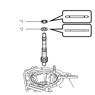
| *1 | Thrust Needle Roller Bearing J |
| *2 | Thrust Bearing Race J (Rear Race) |
Coat the thrust needle roller bearing and thrust bearing race with ATF and install them to the intermediate shaft.
- Thrust Needle Roller Bearing and Thrust Bearing Race Diameter:
Item Inside (mm (in.)) Outside (mm (in.)) Thrust Needle Roller Bearing J 32.1 (1.264) 49.35 (1.943) Thrust Bearing Race J
(Rear Race)32.1 (1.264) 49.0 (1.929)
Install the intermediate shaft to the automatic transmission case sub-assembly.
35761
9.INSTALL REAR PLANETARY RING GEAR
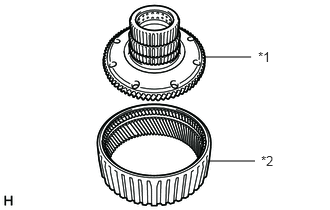
| *1 | Rear Planetary Ring Gear Flange Sub-assembly |
| *2 | Rear Planetary Ring Gear |
Install the rear planetary ring gear to the rear planetary ring gear flange sub-assembly.
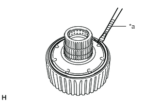
| *a | Protective Tape |
Using a screwdriver, install the snap ring to the rear planetary ring gear flange sub-assembly with rear planetary ring gear.
- NOTICE:
-
Be careful not to damage the rear planetary ring gear flange sub-assembly with rear planetary ring gear.
- HINT:
-
Tape the screwdriver tip before use.
35077D
10.INSTALL REAR PLANETARY RING GEAR FLANGE SUB-ASSEMBLY WITH REAR PLANETARY RING GEAR
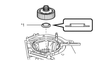
| *1 | Thrust Bearing Race J (Front Race) |
Coat the thrust bearing race with ATF and install it to the rear planetary ring gear flange sub-assembly with rear planetary ring gear.
- Thrust Bearing Race Diameter:
Item Inside (mm (in.)) Outside (mm (in.)) Thrust Bearing Race J
(Front Race)33.4 (1.315.) 49.0 (1.929)
- NOTICE:
-
Be sure to install the thrust bearing race in the correct direction.
Install the rear planetary ring gear flange sub-assembly with rear planetary ring gear to the automatic transmission case sub-assembly.
35797B
11.INSTALL ONE-WAY CLUTCH INNER RACE
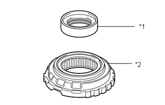
| *1 | One-way Clutch Inner Race |
| *2 | No. 3 One-way Clutch Assembly |
Install the one-way clutch inner race to the No. 3 one-way clutch assembly.
- HINT:
-
Rotate the one-way clutch inner race clockwise to install it.
35770C
12.INSTALL NO. 3 ONE-WAY CLUTCH ASSEMBLY WITH ONE-WAY CLUTCH INNER RACE
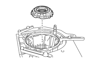
Install the No. 3 one-way clutch assembly with one-way clutch inner race to the automatic transmission case sub-assembly.
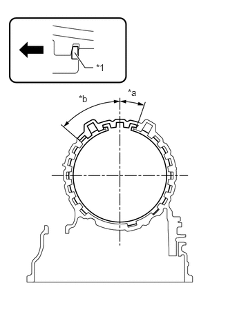
| *1 | Snap Ring |
| *a | 19° |
| *b | 49° |

|
Front Side |
Using SST, install the snap ring to the automatic transmission case sub-assembly.
- SST
- 09350-30020 (09350-07060)
- NOTICE:
- ·
Install the snap ring so that the tapered side is facing out.
·Be sure to install the snap ring so that the ends of the snap ring are within the area shown in the illustration.
35689
13.INSPECT CLEARANCE OF NO. 4 BRAKE
35621V
14.INSTALL NO. 1 BRAKE PISTON
Coat 2 new O-rings with ATF and install them to the No. 1 brake piston.
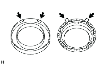
With the No. 1 brake piston return spring sub-assembly installed to the No. 1 brake piston, align the 2 claws of the No. 1 brake piston return spring sub-assembly with the 2 claws of the No. 1 brake cylinder, and then install the No. 1 brake piston to the No. 1 brake cylinder.
35698
15.INSTALL NO. 1 BRAKE CYLINDER WITH NO. 1 BRAKE PISTON
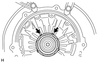
Install the No. 1 brake cylinder with No. 1 brake piston to the automatic transmission case sub-assembly while making sure that the 2 claws of the No. 1 brake cylinder with No. 1 brake piston are positioned as shown in the illustration.
35608J
16.INSTALL NO. 1 BRAKE PISTON RETURN SPRING SUB-ASSEMBLY
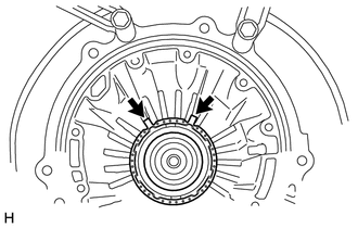
Align the 2 claws of the No. 1 brake piston return spring sub-assembly with the 2 claws of the No. 1 brake cylinder, and then install the No. 1 brake piston return spring sub-assembly to the No. 1 brake piston.
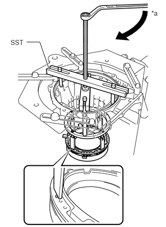
| *a | Turn |
Place SST on the No. 1 brake piston return spring sub-assembly, and compress the No. 1 brake piston return spring sub-assembly with a press.
- SST
- 09380-60012 (09381-06010, 09381-06040, 09381-06050, 09381-06070, 09381-06090, 09381-06100, 09381-06110, 09381-06120)
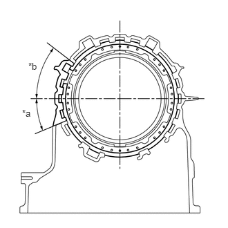
| *a | 22.5° |
| *b | 37.5° |
Using a screwdriver, install the snap ring to the automatic transmission case sub-assembly.
- NOTICE:
- ·
Be sure to install the snap ring so that the ends of the snap ring are within the area shown in the illustration.
·Be careful not to damage the automatic transmission case sub-assembly.
- HINT:
-
Tape the screwdriver tip before use.
35681A
17.INSTALL NO. 1 BRAKE DISC
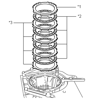
| *1 | No. 1 Brake Flange |
| *2 | No. 1 Brake Disc |
| *3 | No. 1 Brake Plate |
Install the No. 1 brake flange, 4 No. 1 brake discs and 4 No. 1 brake plates to the automatic transmission case sub-assembly.
- NOTICE:
-
Make sure that the No. 1 brake discs, No. 1 brake plates and No. 1 brake flange are installed in the correct order.
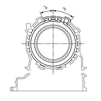
| *a | 22.5° |
| *b | 37.5° |
Using a screwdriver, install the snap ring to the automatic transmission case sub-assembly.
- NOTICE:
- ·
Be sure to install the snap ring so that the ends of the snap ring are within the area shown in the illustration.
·Be careful not to damage the automatic transmission case sub-assembly.
- HINT:
-
Tape the screwdriver tip before use.
35676B
18.INSPECT CLEARANCE OF NO. 1 BRAKE
35719B
19.INSTALL PLANETARY SUN GEAR
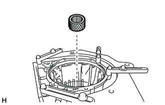
Install the planetary sun gear to the automatic transmission case sub-assembly.
35750
20.INSTALL CENTER PLANETARY GEAR ASSEMBLY
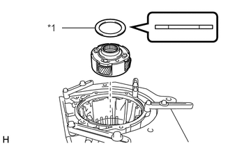
| *1 | Thrust Bearing Race I |
Coat the thrust bearing race with ATF and install it to the center planetary gear assembly.
- Thrust Bearing Race Diameter:
Item Inside (mm (in.)) Outside (mm (in.)) Thrust Bearing Race I 53.7 (2.114) 74.0 (2.913)
Install the center planetary gear assembly to the automatic transmission case sub-assembly.
35763
21.INSTALL CENTER PLANETARY RING GEAR
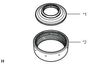
| *1 | Center Planetary Ring Gear Flange |
| *2 | Center Planetary Ring Gear |
Install the center planetary ring gear to the center planetary ring gear flange.
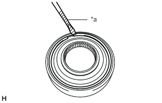
| *a | Protective Tape |
Using a screwdriver, install the snap ring to the center planetary ring gear flange with center planetary ring gear.
- NOTICE:
-
Be careful not to damage the center planetary ring gear flange with center planetary ring gear.
- HINT:
-
Tape the screwdriver tip before use.
35769
22.INSTALL CENTER PLANETARY RING GEAR FLANGE WITH CENTER PLANETARY RING GEAR
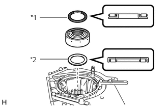
| *1 | Thrust Needle Roller Bearing H |
| *2 | Thrust Needle Roller Bearing I |
Coat the 2 thrust needle roller bearings with ATF and install them to the center planetary ring gear flange with center planetary ring gear.
- Thrust Needle Roller Bearing Diameter:
Item Inside (mm (in.)) Outside (mm (in.)) Thrust Needle Roller Bearing H 63.3 (2.492) 78.8 (3.102) Thrust Needle Roller Bearing I 55.7 (2.193) 76.4 (3.008)
- NOTICE:
-
Be sure to install the thrust needle roller bearing in the correct direction.
Install the center planetary ring gear flange with center planetary ring gear to the automatic transmission case sub-assembly.
35682A
23.INSTALL NO. 2 BRAKE DISC
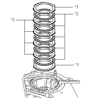
| *1 | No. 2 Brake Flange |
| *2 | No. 2 Brake Disc |
| *3 | No. 2 Brake Plate |
Install the 2 No. 2 brake flanges, 5 No. 2 brake discs and 4 No. 2 brake plates to the automatic transmission case sub-assembly.
- NOTICE:
- ·
Make sure that the No. 2 brake discs, No. 2 brake plates and No. 2 brake flanges are installed in the correct order.
·Install the thicker No. 2 brake flange first, and then install the thinner one.
35622G
24.INSTALL NO. 2 BRAKE PISTON
Coat 2 new O-rings with ATF and install them to the No. 2 brake piston.
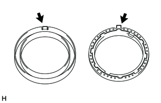
With the No. 2 brake piston return spring sub-assembly installed to the No. 2 brake piston, align the claw of the No. 2 brake piston return spring sub-assembly with the claw of the No. 2 brake cylinder, and then install the No. 2 brake piston to the No. 2 brake cylinder.
- NOTICE:
-
Be careful not to damage the O-rings.
35699
25.INSTALL NO. 2 BRAKE CYLINDER WITH NO. 2 BRAKE PISTON
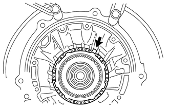
Install the No. 2 brake piston return spring sub-assembly to the automatic transmission case sub-assembly while making sure that the claw of the No. 2 brake piston return spring sub-assembly is positioned as shown in the illustration.
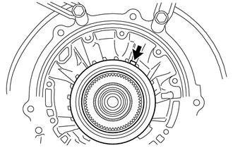
Install the No. 2 brake cylinder with No. 2 brake piston to the automatic transmission case sub-assembly while making sure that the claw of the No. 1 brake cylinder with No. 1 brake piston is positioned as shown in the illustration.
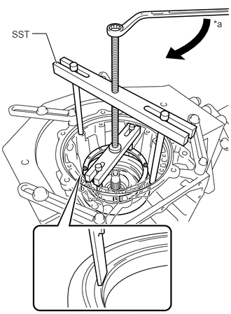
| *a | Turn |
Place SST on the No. 2 brake cylinder, and compress the No. 2 brake piston return spring sub-assembly with a press.
- SST
- 09380-60012 (09381-06010, 09381-06020, 09381-06040, 09381-06050, 09381-06060, 09381-06090, 09381-06100, 09381-06110, 09381-06120)
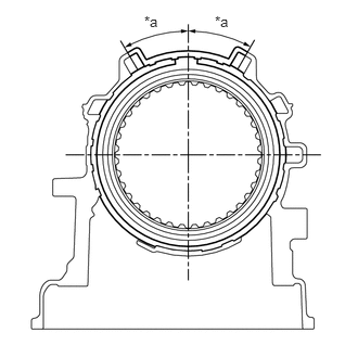
| *a | 30° |
Using a screwdriver, install the snap ring to the automatic transmission case sub-assembly.
- NOTICE:
- ·
Be sure to install the snap ring so that the ends of the snap ring are within the area shown in the illustration.
·Be careful not to damage the automatic transmission case sub-assembly.
- HINT:
-
Tape the screwdriver tip before use.
35678B
26.INSPECT CLEARANCE OF NO. 2 BRAKE
35076C
27.INSTALL FRONT PLANETARY RING GEAR FLANGE SUB-ASSEMBLY
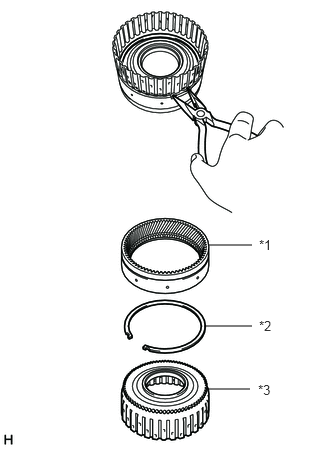
| *1 | Front Planetary Ring Gear |
| *2 | Snap Ring |
| *3 | Front Planetary Ring Gear Flange Sub-assembly |
Set the snap ring onto the front planetary ring gear flange sub-assembly. Using needle-nose pliers, insert the snap ring into the front planetary ring gear while squeezing it, and then expand the snap ring to install it.
- NOTICE:
-
Make sure the snap ring is securely inserted into the groove of the front planetary ring gear.
35743
28.INSTALL FRONT PLANETARY RING GEAR WITH FRONT PLANETARY RING GEAR FLANGE SUB-ASSEMBLY
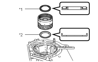
| *1 | Thrust Needle Roller Bearing G |
| *2 | Thrust Bearing Race H |
Coat the thrust needle roller bearing and thrust bearing race with ATF and install them to the front planetary ring gear with front planetary ring gear flange sub-assembly.
- Thrust Needle Roller Bearing and Thrust Bearing Race Diameter:
Item Inside (mm (in.)) Outside (mm (in.)) Thrust Needle Roller Bearing G 63.3 (2.492) 78.8 (3.102) Thrust Bearing Race H 66.3 (2.610) 78.9 (3.106)
- NOTICE:
-
Be sure to install the thrust needle roller bearing and thrust bearing race in the correct direction.
Install the front planetary ring gear with front planetary ring gear flange sub-assembly to the automatic transmission case sub-assembly.
35720
29.INSTALL FRONT PLANETARY GEAR ASSEMBLY
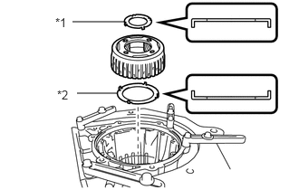
| *1 | Thrust Bearing Race F |
| *2 | Thrust Bearing Race G |
Coat the 2 thrust bearing races with ATF and install them to the front planetary gear assembly.
- Thrust Bearing Race Diameter:
Item Inside (mm (in.)) Outside (mm (in.)) Thrust Bearing Race F 44.0 (1.732) 62.8 (2.472) Thrust Bearing Race G 65.8 (2.591) 86.3 (3.398)
- NOTICE:
-
Be sure to install the thrust bearing race in the correct direction.
Install the front planetary gear assembly to the automatic transmission case sub-assembly.
35709J
30.INSTALL SUN GEAR INPUT DRUM SUB-ASSEMBLY
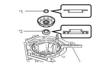
| *1 | Thrust Bearing Race E |
| *2 | Thrust Needle Roller Bearing F |
Coat the thrust needle roller bearing and thrust bearing race with ATF and install them to the sun gear input drum sub-assembly.
- Thrust Needle Roller Bearing and Thrust Bearing Race Diameter:
Item Inside (mm (in.)) Outside (mm (in.)) Thrust Bearing Race E 40.83 (1.607) 52.8 (2.079) Thrust Needle Roller Bearing F 37.1 (1.461) 61.2 (2.409)
- NOTICE:
-
Be sure to install the thrust needle roller bearing and thrust bearing race in the correct direction.
Install the sun gear input drum sub-assembly to the automatic transmission case sub-assembly.
35061
31.INSTALL FORWARD CLUTCH HUB SUB-ASSEMBLY
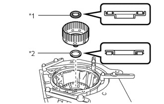
| *1 | Thrust Needle Roller Bearing D |
| *2 | Thrust Needle Roller Bearing E |
Coat the 2 thrust needle roller bearings with ATF and install them to the forward clutch hub sub-assembly.
- Thrust Needle Roller Bearing Diameter:
Item Inside (mm (in.)) Outside (mm (in.)) Thrust Needle Roller Bearing D 33.3 (1.311) 56.6 (2.228) Thrust Needle Roller Bearing E 39.6 (1.559) 52.8 (2.079)
- NOTICE:
-
Be sure to install the thrust needle roller bearing in the correct direction.
Install the forward clutch hub sub-assembly to the automatic transmission case sub-assembly.
35631
32.INSTALL MULTIPLE DISC CLUTCH HUB
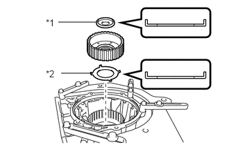
| *1 | Thrust Bearing Race C |
| *2 | Thrust Bearing Race D |
Coat the 2 thrust bearing races with ATF and install them to the multiple disc clutch hub.
- Thrust Bearing Race Diameter:
Item Inside (mm (in.)) Outside (mm (in.)) Thrust Bearing Race C 22.6 (0.866) 44.8 (1.764) Thrust Bearing Race D 38.4 (1.512) 56.5 (2.224)
- NOTICE:
-
Be sure to install the thrust bearing race in the correct direction.
Install the multiple disc clutch hub to the automatic transmission case sub-assembly.
35606A
33.INSTALL DIRECT CLUTCH PISTON SUB-ASSEMBLY
Coat 2 new O-rings with ATF, and install them to the direct clutch piston sub-assembly.
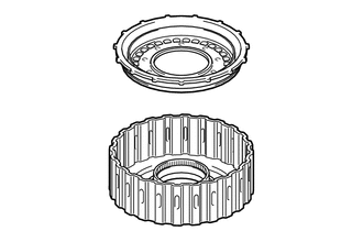
Install the direct clutch piston sub-assembly to the direct clutch drum sub-assembly.
- NOTICE:
-
Be careful not to damage the O-rings.
35669
34.INSTALL NO. 2 CLUTCH BALANCER
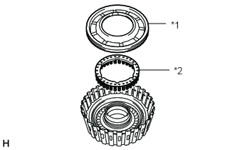
| *1 | No. 2 Clutch Balancer |
| *2 | Direct Clutch Return Spring Sub-assembly |
Install the direct clutch return spring sub-assembly to the direct clutch piston sub-assembly.
Coat a new O-ring with ATF, and install it to the No. 2 clutch balancer.
Install the No. 2 clutch balancer to the direct clutch drum sub-assembly.
- NOTICE:
-
Be careful not to damage the O-ring.
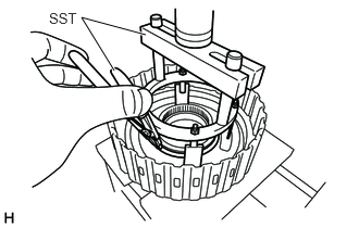
Place SST on the No. 2 clutch balancer, and compress the direct clutch return spring sub-assembly with a press.
- SST
- 09380-60012 (09381-06030, 09381-06040, 09381-06080, 09381-06100, 09381-06110)
- NOTICE:
-
Stop pressing when the spring sheet is lowered to the place 1 to 2 mm (0.0394 to 0.0787 in.) from the snap ring groove to prevent the spring sheet from being deformed.
Using SST, install the snap ring.
- SST
- 09350-30020 (09350-07070)
- NOTICE:
-
Do not expand the snap ring excessively.
35667A
35.INSTALL NO. 2 CLUTCH DISC (DIRECT CLUTCH DISC)
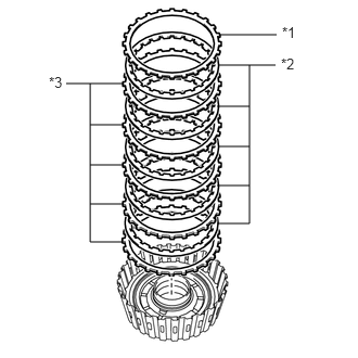
| *1 | Direct Clutch Flange |
| *2 | No. 2 Clutch Disc |
| *3 | No. 2 Clutch Plate |
Install the 5 No. 2 clutch plates, 5 No. 2 clutch discs and direct clutch flange to the direct clutch drum sub-assembly.
- NOTICE:
-
Make sure that the No. 2 clutch discs, No. 2 clutch plates and direct clutch flange are installed in the correct order.

| *a | Protective Tape |
Using a screwdriver, install the snap ring to the direct clutch drum sub-assembly.
- NOTICE:
-
Be careful not to damage the direct clutch drum sub-assembly.
- HINT:
-
Tape the screwdriver tip before use.
35675C
36.INSPECT CLEARANCE OF NO. 2 CLUTCH (DIRECT CLUTCH)
35612B
37.INSTALL FORWARD CLUTCH PISTON
Coat a new O-ring with ATF, and install it to the input shaft sub-assembly.
Coat a new O-ring with ATF, and install it to the forward clutch piston.
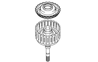
Install the forward clutch piston to the input shaft sub-assembly.
- NOTICE:
-
Be careful not to damage the O-rings.
35668
38.INSTALL NO. 1 CLUTCH BALANCER
Coat a new O-ring with ATF, and install it to the No. 1 clutch balancer.
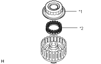
| *1 | No. 1 Clutch Balancer |
| *2 | Forward Clutch Return Spring Sub-assembly |
Install the forward clutch return spring sub-assembly and No. 1 clutch balancer to the input shaft sub-assembly.
- NOTICE:
-
Be careful not to damage the O-ring.
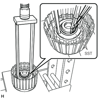
Place SST on the No. 1 clutch balancer, and compress the forward clutch return spring sub-assembly with a press.
- SST
- 09387-00110
- NOTICE:
-
Stop pressing when the spring sheet is lowered to the place 1 to 2 mm (0.0394 to 0.0787 in.) from the snap ring groove to prevent the spring sheet from being deformed.
Using SST, install the snap ring.
- SST
- 09350-30020 (09350-07070)
- NOTICE:
-
Do not expand the snap ring excessively.
35633B
39.INSTALL NO. 1 CLUTCH DISC (FORWARD CLUTCH DISC)

| *1 | Forward Clutch Flange |
| *2 | No. 1 Clutch Disc |
| *3 | No. 1 Clutch Plate |
Install the 5 No. 1 clutch plates, 5 No. 1 clutch discs and forward clutch flange to the input shaft sub-assembly.
- NOTICE:
-
Make sure that the No. 1 clutch discs, No. 1 clutch plates and forward clutch flange are installed in the correct order.
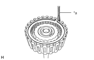
| *a | Protective Tape |
Using a screwdriver, install the snap ring.
- NOTICE:
-
Be careful not to damage the input shaft sub-assembly.
- HINT:
-
Tape the screwdriver tip before use.
35635
40.INSPECT CLEARANCE OF NO. 1 CLUTCH (FORWARD CLUTCH)
35617
41.INSTALL CLUTCH DRUM OIL SEAL RING
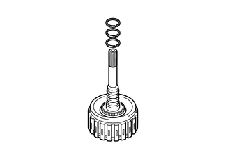
Coat 3 new clutch drum oil seal rings with ATF and install them to the input shaft sub-assembly.
- NOTICE:
-
Do not expand the clutch drum oil seal ring ends excessively.
- HINT:
-
After installing the clutch drum oil seal rings, check that they rotate smoothly.
35605A
42.INSTALL DIRECT CLUTCH DRUM SUB-ASSEMBLY
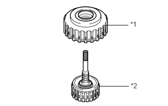
| *1 | Direct Clutch Drum Sub-assembly |
| *2 | Input Shaft Sub-assembly |
Install the direct clutch drum sub-assembly to the input shaft sub-assembly.
43.INSTALL CLUTCH DRUM AND INPUT SHAFT ASSEMBLY
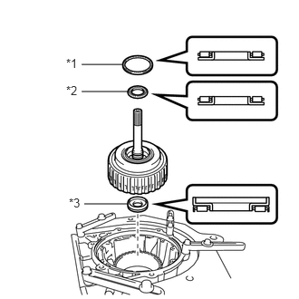
| *1 | Thrust Needle Roller Bearing A |
| *2 | Thrust Needle Roller Bearing B |
| *3 | Thrust Needle Roller Bearing C |
Coat the 3 thrust needle roller bearings with ATF and install them to the clutch drum and input shaft assembly.
- Thrust Needle Roller Bearing Diameter:
Item Inside (mm (in.)) Outside (mm (in.)) Thrust Needle Roller Bearing A 71.9 (2.831) 85.6 (3.370) Thrust Needle Roller Bearing B 34.6 (1.362) 52.0 (2.047) Thrust Needle Roller Bearing C 21.3 (0.839) 41.1 (1.618)
- NOTICE:
-
Be sure to install the thrust needle roller bearing in the correct direction.
Install the clutch drum and input shaft assembly to the automatic transmission case sub-assembly.
44.INSTALL OIL PUMP ASSEMBLY
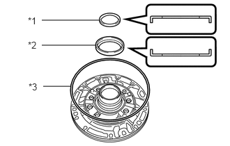
| *1 | Thrust Bearing Race B |
| *2 | Thrust Bearing Race A |
| *3 | Oil Pump O-ring |
Coat the 2 thrust bearing races with ATF and install them to the oil pump assembly.
- Race Diameter:
Item Inside (mm (in.)) Outside (mm (in.)) Thrust Bearing Race B 40.0 (1.575) 52.8 (2.079) Thrust Bearing Race A 74.2 (2.921) 87.74 (3.454)
- NOTICE:
-
Be sure to install the thrust bearing race in the correct direction.
Coat a new oil pump O-ring with ATF, and install it to the oil pump assembly.
Set the oil pump assembly on the input shaft, and align the bolt holes of the oil pump assembly with the automatic transmission case sub-assembly.
- NOTICE:
-
Be careful not to damage the oil pump O-ring.
Temporarily install the oil pump assembly to the automatic transmission case sub-assembly.
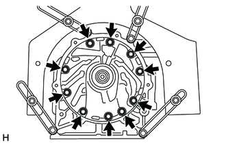
Install the oil pump assembly with the 10 bolts.
- Torque:
- 21.1 N*m (215 kgf*cm, 16 ft.*lbf)
35506F
45.INSTALL MANUAL VALVE LEVER SHAFT OIL SEAL
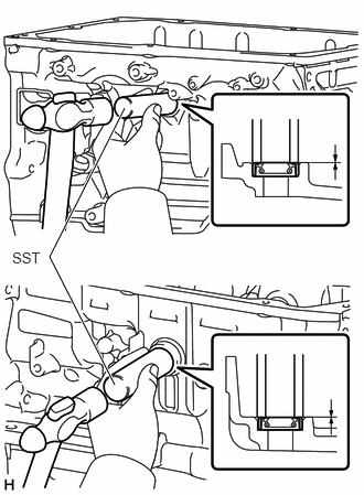
Using SST and a hammer, drive in 2 new manual valve lever shaft oil seals to the automatic transmission case sub-assembly.
- SST
- 09350-30020 (09350-07110)
- Standard Depth:
-0.5 to 0.5 mm (-0.0196 to 0.0196 in.)
Coat the lip of the manual valve lever shaft oil seal with MP grease.
35505
46.INSTALL MANUAL VALVE LEVER SUB-ASSEMBLY
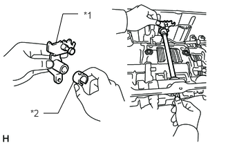
| *1 | Manual Valve Lever Sub-assembly |
| *2 | Spacer |
Install a new spacer to the manual valve lever sub-assembly.
Install the manual valve lever shaft to the automatic transmission case sub-assembly through the manual valve lever sub-assembly.
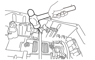
Using a hammer, drive in a new spring pin.
Turn the spacer and manual valve lever shaft to align the smaller hole on the spacer with the indent on the manual valve lever sub-assembly.
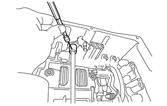
Using a 3 mm pin punch and a hammer, stake the spacer.
Check that the spacer does not turn.
Make sure that the shaft rotates smoothly.
35556
47.INSTALL PARKING LOCK PAWL SHAFT
Install the E-ring to the parking lock pawl shaft.
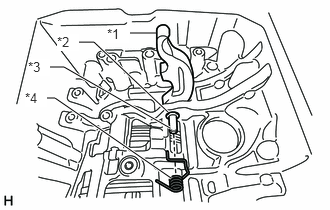
| *1 | Parking Lock Pawl |
| *2 | E-ring |
| *3 | Parking Lock Pawl Shaft |
| *4 | Spring |
Install the parking lock pawl, parking lock pawl shaft and spring to the automatic transmission case sub-assembly.
35501
48.INSTALL PARKING LOCK ROD SUB-ASSEMBLY
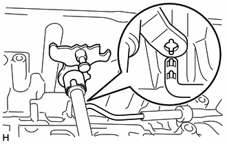
Install the parking lock rod sub-assembly to the manual valve lever sub-assembly.
35595
49.INSTALL PARKING LOCK PAWL BRACKET
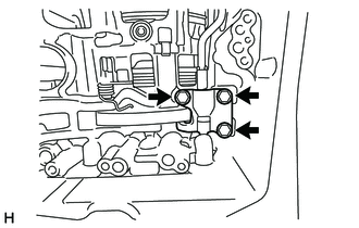
Install the parking lock pawl bracket to the automatic transmission case sub-assembly with the 3 bolts.
- Torque:
- 18 N*m (184 kgf*cm, 13 ft.*lbf)
Move the manual valve lever sub-assembly to P, and check the output shaft is locked by the parking lock pawl.
35159
50.INSTALL BRAKE DRUM GASKET
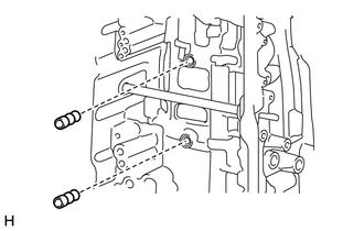
Coat 2 new brake drum gaskets with ATF and install them to the automatic transmission case sub-assembly.
35145C
51.INSTALL TRANSMISSION CASE GASKET
52.INSTALL MANUAL VALVE
35410
53.INSTALL TRANSMISSION VALVE BODY ASSEMBLY
35330
54.INSTALL VALVE BODY OIL STRAINER ASSEMBLY
82125J
55.INSTALL TRANSMISSION WIRE
82125J
56.CONNECT TRANSMISSION WIRE
35106
57.INSTALL AUTOMATIC TRANSMISSION OIL PAN SUB-ASSEMBLY
35111
58.INSTALL AUTOMATIC TRANSMISSION HOUSING
Clean and degrease the bolts and bolt holes with non-residue solvent.
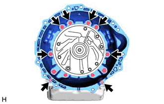
Install the automatic transmission housing to the automatic transmission case sub-assembly with the 8 bolts.
- Torque:
- 33.9 N*m (346 kgf*cm, 25 ft.*lbf)
Apply adhesive to 2 or 3 threads on the end of the 4 bolts.
- Adhesive:
Toyota Genuine Adhesive 1344, Three Bond 1344 or equivalent
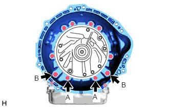
Install 4 bolts to the automatic transmission housing.
- Torque:
- for bolt A (M10 bolt) : 33.9 N*m (346 kgf*cm, 25 ft.*lbf)
- for bolt B (M12 bolt) : 56.8 N*m (579 kgf*cm, 42 ft.*lbf)
35108R
59.INSTALL AUTOMATIC TRANSMISSION EXTENSION HOUSING OIL SEAL
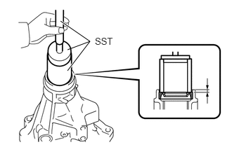
Using SST and a press, install a new automatic transmission extension housing oil seal to the extension housing sub-assembly.
- Standard Depth:
5.4 to 5.8 mm (0.213 to 0.228 in.)
- SST
- 09950-60011 (09951-00460, 09951-00550, 09952-06010)
09950-70010 (09951-07150)
09710-14013 (09710-00021)
Coat the lip of the automatic transmission extension housing oil seal with MP grease.
60.INSTALL EXTENSION HOUSING DUST DEFLECTOR
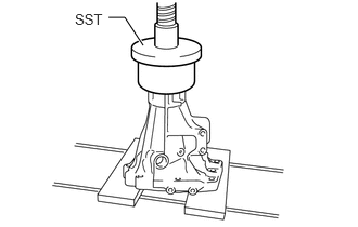
Using SST and a press, install a new extension housing dust deflector to the extension housing sub-assembly.
- SST
- 09550-55012 (09550-05081)
35108
61.INSTALL EXTENSION HOUSING SUB-ASSEMBLY
Clean and degrease the threads of the 8 bolts, bolt holes and the contact surfaces of the automatic transmission case sub-assembly and extension housing sub-assembly with non-residue solvent.
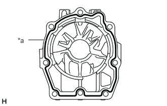
| *a | Seal Packing |
Apply seal packing to the extension housing sub-assembly as shown in the illustration.
- Seal Packing:
Toyota Genuine Seal Packing 1281, Three Bond 1281 or equivalent
- NOTICE:
- ·
Apply seal packing in a continuous line (width 1.2 mm (0.0472 in.)) along the sealing surface.
·After applying seal packing, install the extension housing sub-assembly to the automatic transmission case sub-assembly within 3 minutes and tighten the bolts within 10 minutes.
Apply adhesive to 2 or 3 threads on the end of the 8 bolts.
- Adhesive:
Toyota Genuine Adhesive 1344, Three Bond 1344 or equivalent
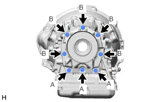
Install the extension housing sub-assembly to the automatic transmission case sub-assembly with the 8 bolts.
- Torque:
- 33.9 N*m (346 kgf*cm, 25 ft.*lbf)
- Bolt Length:
Bolt A 40 mm (1.57 in.) Bolt B 45 mm (1.77 in.)
62.INSTALL OIL COOLER TUBE UNION
Coat 2 new O-rings with ATF and install them to the 2 oil cooler tube unions.
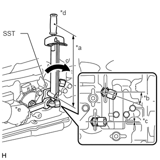
| *a | Torque Wrench Fulcrum Length |
| *b | 18° to 22° |
| *c | -2° to 2° |
| *d | Turn |
| *e | Hold |
Using SST, install the 2 oil cooler tube unions to the automatic transmission case sub-assembly.
- SST
- 09268-78010
- Specified tightening torque:
29.4 N*m (300 kgf*cm, 22 ft.*lbf)
- HINT:
- ·
Calculate the torque wrench reading when changing the fulcrum length of the torque wrench.
·When using SST (fulcrum length of 34.5 mm (1.3583 in.)) + torque wrench (fulcrum length of 180 mm (7.0866 in.)): 24.7 N*m (252 kgf*cm, 18 ft.*lbf)
35104A
63.INSTALL AUTOMATIC TRANSMISSION CASE PLUG
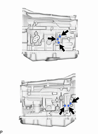
Coat 6 new O-rings with ATF, and install them to the 6 automatic transmission case plugs.
Install the 6 automatic transmission case plugs to the automatic transmission case sub-assembly.
- Torque:
- 7.4 N*m (75 kgf*cm, 65 in.*lbf)
Coat a new O-ring with ATF, and install it to the automatic transmission case plug.
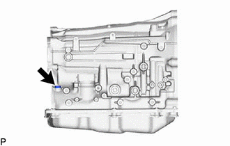
Using a T55 "TORX" socket wrench, install the automatic transmission case plug to the automatic transmission case sub-assembly.
- Torque:
- 39.2 N*m (400 kgf*cm, 29 ft.*lbf)
35015P
64.INSTALL REFILL PLUG
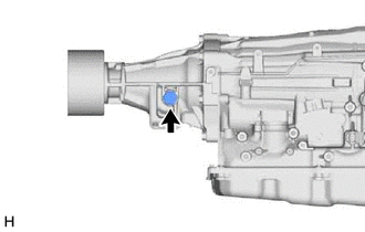
Coat a new O-ring with ATF, and install it to the refill plug.
Install the refill plug to the automatic transmission case sub-assembly.
- Torque:
- 39.2 N*m (400 kgf*cm, 29 ft.*lbf)
84540
65.INSTALL PARK/NEUTRAL POSITION SWITCH ASSEMBLY
35573
66.INSTALL TRANSMISSION CONTROL SHAFT LEVER LH
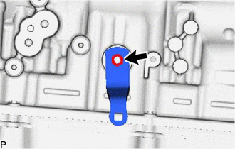
Install the transmission control shaft lever LH to the manual valve lever shaft with the spring washer and nut.
- Torque:
- 15.7 N*m (160 kgf*cm, 12 ft.*lbf)
89413R
67.INSTALL TRANSMISSION REVOLUTION SENSOR (SP2)
89413N
68.INSTALL TRANSMISSION REVOLUTION SENSOR (NT)
35104V
69.INSTALL BREATHER PLUG HOSE
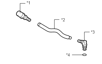
| *1 | Breather Plug Sub-assembly |
| *2 | Breather Plug Hose |
| *3 | Breather Plug |
| *4 | O-ring |
Install the breather plug sub-assembly and breather plug to the breather plug hose.
Coat a new O-ring with ATF, and install it to the breather plug.
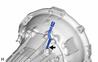
Install the breather plug hose to the automatic transmission case sub-assembly.
- NOTICE:
-
Be careful not to damage the O-rings.