AC60E AUTOMATIC TRANSMISSION / TRANSAXLE AUTOMATIC TRANSMISSION UNIT(for 7GR-FKS) DISASSEMBLY
PROCEDURE

 35104V
1.REMOVE BREATHER PLUG HOSE
35104V
1.REMOVE BREATHER PLUG HOSE
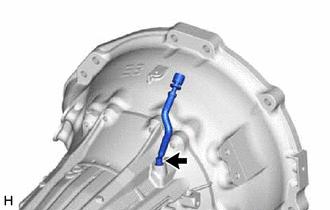
Remove the breather plug hose from the automatic transmission case sub-assembly.
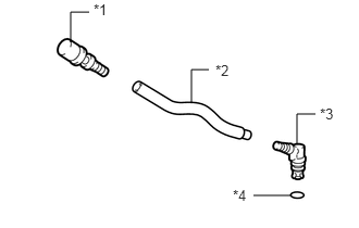
| *1 | Breather Plug Sub-assembly |
| *2 | Breather Plug Hose |
| *3 | Breather Plug |
| *4 | O-ring |
Remove the O-ring from the breather plug.
Remove the breather plug sub-assembly and breather plug from the breather plug hose.
89413N
2.REMOVE TRANSMISSION REVOLUTION SENSOR (NT)
89413R
3.REMOVE TRANSMISSION REVOLUTION SENSOR (SP2)
35573
4.REMOVE TRANSMISSION CONTROL SHAFT LEVER LH
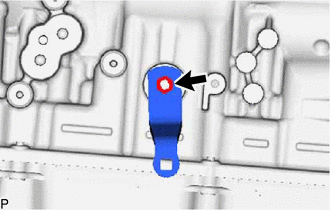
Remove the nut, spring washer and transmission control shaft lever LH from the manual valve lever shaft.
84540
5.REMOVE PARK/NEUTRAL POSITION SWITCH ASSEMBLY
35015P
6.REMOVE REFILL PLUG
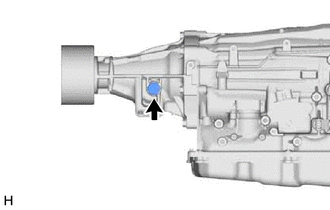
Remove the refill plug from the extension housing sub-assembly.
Remove the O-ring from the refill plug.
35104A
7.REMOVE AUTOMATIC TRANSMISSION CASE PLUG
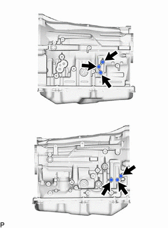
Remove the 6 automatic transmission case plugs from the automatic transmission case sub-assembly.
Remove the 6 O-rings from the 6 automatic transmission case plugs.
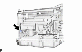
Using a T55 "TORX" socket wrench, remove the automatic transmission case plug from the automatic transmission case sub-assembly.
Remove the O-ring from the automatic transmission case plug.
8.REMOVE OIL COOLER TUBE UNION
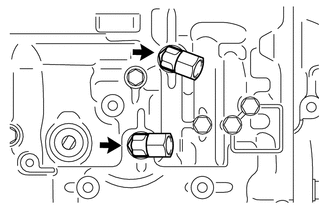
Remove the 2 oil cooler tube unions from the automatic transmission case sub-assembly.
Remove the 2 O-rings from the 2 oil cooler tube unions.
9.REMOVE EXTENSION HOUSING DUST DEFLECTOR
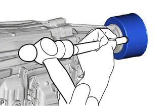
Using a brass bar and hammer, tap out the extension housing dust deflector from the extension housing sub-assembly.
- NOTICE:
-
Be careful not to damage the extension housing sub-assembly.
35108
10.REMOVE EXTENSION HOUSING SUB-ASSEMBLY
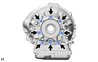
Remove the 8 bolts and extension housing sub-assembly from the automatic transmission case sub-assembly.
- HINT:
-
Use a brass bar and hammer to remove the extension housing.
35108R
11.REMOVE AUTOMATIC TRANSMISSION EXTENSION HOUSING OIL SEAL
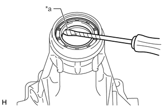
| *a | Protective Tape |
Using a screwdriver, pry out the automatic transmission extension housing oil seal from the extension housing sub-assembly.
- NOTICE:
-
Be careful not to damage the extension housing sub-assembly.
- HINT:
-
Tape the screwdriver tip before use.
35111
12.REMOVE AUTOMATIC TRANSMISSION HOUSING
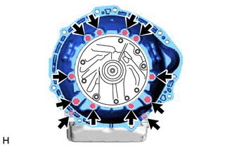
Remove the 12 bolts and automatic transmission housing from the automatic transmission case sub-assembly.
35104
13.SECURE AUTOMATIC TRANSMISSION CASE SUB-ASSEMBLY
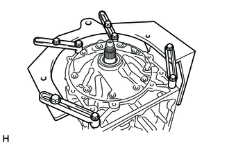
Install the automatic transmission case sub-assembly to an overhaul attachment.
35106
14.REMOVE AUTOMATIC TRANSMISSION OIL PAN SUB-ASSEMBLY
82125J
15.DISCONNECT TRANSMISSION WIRE
82125J
16.REMOVE TRANSMISSION WIRE
35330
17.REMOVE VALVE BODY OIL STRAINER ASSEMBLY
35410
18.REMOVE TRANSMISSION VALVE BODY ASSEMBLY
19.REMOVE MANUAL VALVE
35145C
20.REMOVE TRANSMISSION CASE GASKET
35159
21.REMOVE BRAKE DRUM GASKET
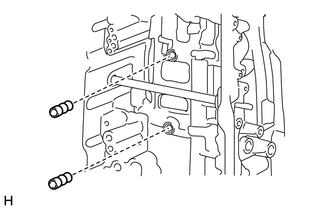
Remove the 2 brake drum gaskets from the automatic transmission case sub-assembly.
35595
22.REMOVE PARKING LOCK PAWL BRACKET
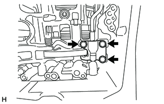
Remove the 3 bolts and parking lock pawl bracket from the automatic transmission case sub-assembly.
35501
23.REMOVE PARKING LOCK ROD SUB-ASSEMBLY
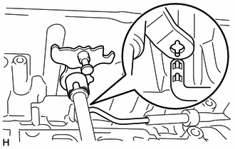
Remove the parking lock rod sub-assembly from the manual valve lever sub-assembly.
35556
24.REMOVE PARKING LOCK PAWL SHAFT
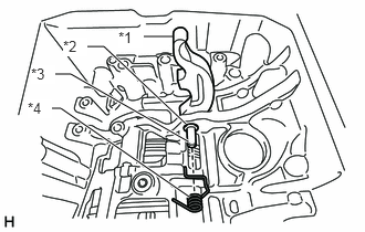
| *1 | Parking Lock Pawl |
| *2 | E-ring |
| *3 | Parking Lock Pawl Shaft |
| *4 | Spring |
Pull out the parking lock pawl shaft from the front side, and remove the parking lock pawl and spring.
Remove the E-ring from the parking lock pawl shaft.
35505
25.REMOVE MANUAL VALVE LEVER SUB-ASSEMBLY
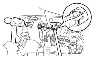
| *a | Protective Tape |
Using a screwdriver and hammer, cut off the spacer and remove it from the manual valve lever shaft.
- NOTICE:
-
Be careful not to damage the manual valve lever shaft.
- HINT:
-
Tape the screwdriver tip before use.
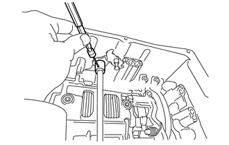
Using a 3 mm pin punch and hammer, drive out the spring pin.
- HINT:
-
Slowly drive out the spring pin so that it does not fall into the automatic transmission case sub-assembly.
Pull the manual valve lever shaft out through the case and remove the manual valve lever sub-assembly.
35506F
26.REMOVE MANUAL VALVE LEVER SHAFT OIL SEAL
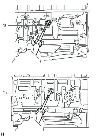
| *a | Protective Tape |
Using a screwdriver, pry out the 2 manual valve lever shaft oil seals from the automatic transmission case sub-assembly.
- NOTICE:
-
Be careful not to damage the automatic transmission case sub-assembly.
- HINT:
-
Tape the screwdriver tip before use.
27.REMOVE OIL PUMP ASSEMBLY
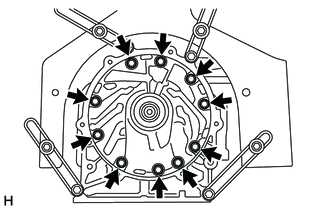
Remove the 10 bolts.
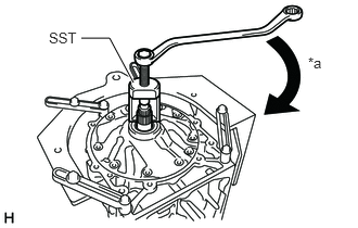
| *a | Turn |
Using SST, pull out the oil pump assembly from the automatic transmission case sub-assembly.
- SST
- 09610-20012
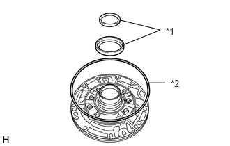
| *1 | Thrust Bearing Race |
| *2 | Oil Pump O-ring |
Remove the 2 thrust bearing races from the oil pump assembly.
Remove the oil pump O-ring from the oil pump assembly.
28.REMOVE CLUTCH DRUM AND INPUT SHAFT ASSEMBLY
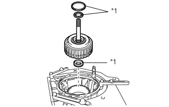
| *1 | Thrust Needle Roller Bearing |
Remove the clutch drum and input shaft assembly from the automatic transmission case sub-assembly.
Remove the 3 thrust needle roller bearings from the clutch drum and input shaft assembly.
35605A
29.REMOVE DIRECT CLUTCH DRUM SUB-ASSEMBLY
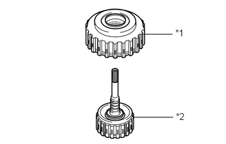
| *1 | Direct Clutch Drum Sub-assembly |
| *2 | Input Shaft Sub-assembly |
Remove the direct clutch drum sub-assembly from the input shaft sub-assembly.
35635
30.INSPECT CLEARANCE OF NO. 1 CLUTCH (FORWARD CLUTCH)
35617
31.REMOVE CLUTCH DRUM OIL SEAL RING
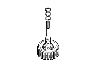
Remove the 3 clutch drum oil seal rings from the input shaft sub-assembly.
35633B
32.REMOVE NO. 1 CLUTCH DISC (FORWARD CLUTCH DISC)
Secure the input shaft sub-assembly in a vise between aluminum plates.
- NOTICE:
-
Do not overtighten the vise.
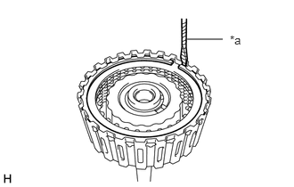
| *a | Protective Tape |
Using a screwdriver, remove the snap ring.
- NOTICE:
-
Be careful not to damage the input shaft sub-assembly.
- HINT:
-
Tape the screwdriver tip before use.
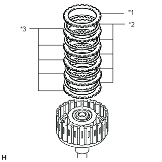
| *1 | Forward Clutch Flange |
| *2 | No. 1 Clutch Disc |
| *3 | No. 1 Clutch Plate |
Remove the forward clutch flange, 5 No. 1 clutch discs and 5 No. 1 clutch plates from the input shaft sub-assembly.
35633B
33.INSPECT NO. 1 CLUTCH DISC (FORWARD CLUTCH DISC)
35668
34.REMOVE NO. 1 CLUTCH BALANCER
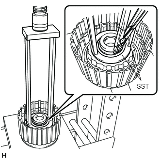
Place SST on the No. 1 clutch balancer, and compress the forward clutch return spring sub-assembly with a press.
- SST
- 09387-00110
Using SST, remove the snap ring.
- SST
- 09350-30020 (09350-07070)
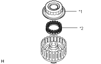
| *1 | No. 1 Clutch Balancer |
| *2 | Forward Clutch Return Spring Sub-assembly |
Remove the No. 1 clutch balancer and forward clutch return spring sub-assembly from the input shaft sub-assembly.
Remove the O-ring from the No. 1 clutch balancer.
35603A
35.INSPECT FORWARD CLUTCH RETURN SPRING SUB-ASSEMBLY
35612B
36.REMOVE FORWARD CLUTCH PISTON
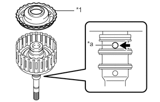
| *1 | Forward Clutch Piston |
| *a | Oil Hole |
While holding the forward clutch piston, apply compressed air to the oil hole of the input shaft sub-assembly to remove the forward clutch piston from the input shaft sub-assembly.
Remove the O-ring from the forward clutch piston.
Remove the O-ring from the input shaft sub-assembly.
37.INSPECT INPUT SHAFT SUB-ASSEMBLY
35675C
38.INSPECT CLEARANCE OF NO. 2 CLUTCH (DIRECT CLUTCH)
35667A
39.REMOVE NO. 2 CLUTCH DISC (DIRECT CLUTCH DISC)

| *a | Protective Tape |
Using a screwdriver, remove the snap ring from the direct clutch drum sub-assembly.
- NOTICE:
-
Be careful not to damage the direct clutch drum sub-assembly.
- HINT:
-
Tape the screwdriver tip before use.
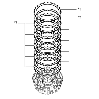
| *1 | Direct Clutch Flange |
| *2 | No. 2 Clutch Disc |
| *3 | No. 2 Clutch Plate |
Remove the direct clutch flange, 5 No. 2 clutch discs and 5 No. 2 clutch plates from the direct clutch drum sub-assembly.
35667A
40.INSPECT NO. 2 CLUTCH DISC (DIRECT CLUTCH DISC)
35669
41.REMOVE NO. 2 CLUTCH BALANCER
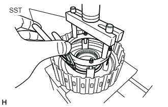
Place SST on the No. 2 clutch balancer, and compress the direct clutch return spring sub-assembly with a press.
- SST
- 09380-60012 (09381-06030, 09381-06040, 09381-06080, 09381-06100, 09381-06110)
Using SST, remove the snap ring.
- SST
- 09350-30020 (09350-07070)
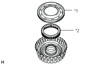
| *1 | No. 2 Clutch Balancer |
| *2 | Direct Clutch Return Spring Sub-assembly |
Remove the No. 2 clutch balancer and direct clutch return spring sub-assembly from the direct clutch drum sub-assembly.
Remove the O-ring from the No. 2 clutch balancer.
35604
42.INSPECT DIRECT CLUTCH RETURN SPRING SUB-ASSEMBLY
35606A
43.REMOVE DIRECT CLUTCH PISTON SUB-ASSEMBLY
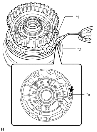
| *1 | Oil Pump Assembly |
| *2 | Torque Converter Assembly |
| *a | Oil Hole |
Place the oil pump assembly onto the torque converter assembly, and then place the direct clutch drum sub-assembly onto the oil pump assembly.
While holding the direct clutch piston, apply compressed air to the oil hole of the oil pump assembly to remove the direct clutch piston sub-assembly from the direct clutch drum sub-assembly.
Remove the 2 O-rings from the direct clutch piston.
35605A
44.INSPECT DIRECT CLUTCH DRUM SUB-ASSEMBLY
35631
45.REMOVE MULTIPLE DISC CLUTCH HUB

| *1 | Thrust Bearing Race |
Remove the multiple disc clutch hub from the automatic transmission case sub-assembly.
Remove the 2 thrust bearing races from the multiple disc clutch hub.
35061
46.REMOVE FORWARD CLUTCH HUB SUB-ASSEMBLY
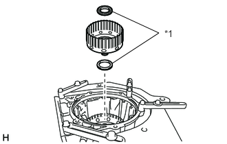
| *1 | Thrust Needle Roller Bearing |
Remove the forward clutch hub sub-assembly from the automatic transmission case sub-assembly.
Remove the 2 thrust needle roller bearings from the forward clutch hub sub-assembly.
35061
47.INSPECT FORWARD CLUTCH HUB SUB-ASSEMBLY
35709J
48.REMOVE SUN GEAR INPUT DRUM SUB-ASSEMBLY
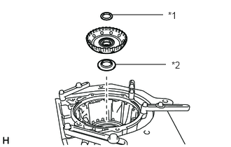
| *1 | Thrust Bearing Race |
| *2 | Thrust Needle Roller Bearing |
Remove the sun gear input drum sub-assembly from the automatic transmission case sub-assembly.
Remove the thrust needle roller bearing and thrust bearing race from the sun gear input drum sub-assembly.
35709J
49.INSPECT SUN GEAR INPUT DRUM SUB-ASSEMBLY
35720
50.REMOVE FRONT PLANETARY GEAR ASSEMBLY
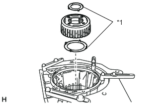
| *1 | Thrust Bearing Race |
Remove the front planetary gear assembly from the automatic transmission case sub-assembly.
Remove the 2 thrust bearing races from the front planetary gear assembly.
35720
51.INSPECT FRONT PLANETARY GEAR ASSEMBLY
35743
52.REMOVE FRONT PLANETARY RING GEAR WITH FRONT PLANETARY RING GEAR FLANGE SUB-ASSEMBLY
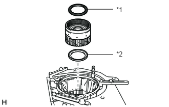
| *1 | Thrust Needle Roller Bearing |
| *2 | Thrust Bearing Race |
Remove the front planetary ring gear with front planetary ring gear flange sub-assembly from the automatic transmission case sub-assembly.
Remove the thrust needle roller bearing and thrust bearing race from the front planetary ring gear with front planetary ring gear flange sub-assembly.
35076C
53.REMOVE FRONT PLANETARY RING GEAR FLANGE SUB-ASSEMBLY
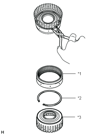
| *1 | Front Planetary Ring Gear |
| *2 | Snap Ring |
| *3 | Front Planetary Ring Gear Flange Sub-assembly |
Using needle-nose pliers, remove the snap ring and front planetary ring gear flange sub-assembly from the front planetary ring gear.
35076C
54.INSPECT FRONT PLANETARY RING GEAR FLANGE SUB-ASSEMBLY
35682A
55.INSPECT CLEARANCE OF NO. 2 BRAKE
35699
56.REMOVE NO. 2 BRAKE CYLINDER WITH NO. 2 BRAKE PISTON
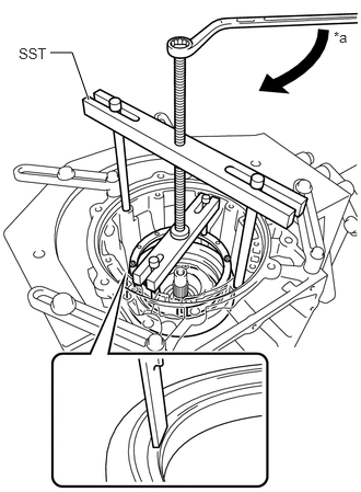
| *a | Turn |
Place SST on the No. 2 brake cylinder, and compress the No. 2 brake piston return spring sub-assembly with a press.
- SST
- 09380-60012 (09381-06010, 09381-06020, 09381-06040, 09381-06050, 09381-06060, 09381-06090, 09381-06100, 09381-06110, 09381-06120)
Using a screwdriver, remove the snap ring from the automatic transmission case sub-assembly.
- NOTICE:
-
Be careful not to damage the automatic transmission case sub-assembly.
- HINT:
-
Tape the screwdriver tip before use.
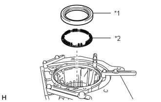
| *1 | No. 2 Brake Cylinder with No. 2 Brake Piston |
| *2 | No. 2 Brake Piston Return Spring Sub-assembly |
Remove the No. 2 brake cylinder with No. 2 brake piston and No. 2 brake piston return spring sub-assembly from the automatic transmission case sub-assembly.
35045
57.INSPECT NO. 2 BRAKE PISTON RETURN SPRING SUB-ASSEMBLY
35622G
58.REMOVE NO. 2 BRAKE PISTON
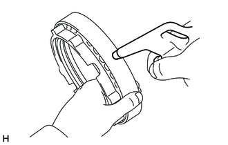
While holding the No. 2 brake piston, apply compressed air to the oil hole of the No. 2 brake cylinder to remove the No. 2 brake piston from the No. 2 brake cylinder.
Remove the 2 O-rings from the No. 2 brake piston.
35682A
59.REMOVE NO. 2 BRAKE DISC
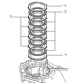
| *1 | No. 2 Brake Flange |
| *2 | No. 2 Brake Disc |
| *3 | No. 2 Brake Plate |
Remove the 2 No. 2 brake flanges, 5 No. 2 brake discs and 4 No. 2 brake plates from the automatic transmission case sub-assembly.
35682A
60.INSPECT NO. 2 BRAKE DISC
35769
61.REMOVE CENTER PLANETARY RING GEAR FLANGE WITH CENTER PLANETARY RING GEAR
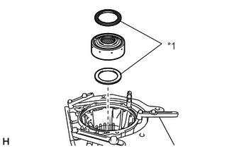
| *1 | Thrust Needle Roller Bearing |
Remove the center planetary ring gear flange with center planetary ring gear from the automatic transmission case sub-assembly.
Remove the 2 thrust needle roller bearings from the center planetary ring gear flange with center planetary ring gear.
35763
62.REMOVE CENTER PLANETARY RING GEAR
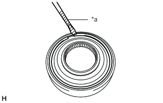
| *a | Protective Tape |
Using a screwdriver, remove the snap ring from the center planetary ring gear flange with center planetary ring gear.
- NOTICE:
-
Be careful not to damage the center planetary ring gear flange with center planetary ring gear.
- HINT:
-
Tape the screwdriver tip before use.
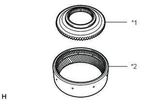
| *1 | Center Planetary Ring Gear Flange |
| *2 | Center Planetary Ring Gear |
Remove the center planetary ring gear from the center planetary ring gear flange.
35750
63.REMOVE CENTER PLANETARY GEAR ASSEMBLY
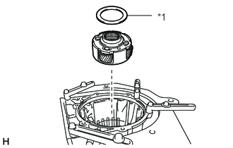
| *1 | Thrust Bearing Race |
Remove the center planetary gear assembly from the automatic transmission case sub-assembly.
Remove the thrust bearing race from the center planetary gear assembly.
35750
64.INSPECT CENTER PLANETARY GEAR ASSEMBLY
35719B
65.REMOVE PLANETARY SUN GEAR
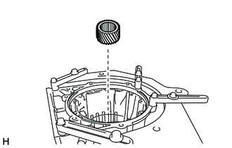
Remove the planetary sun gear from the automatic transmission case sub-assembly.
35681A
66.INSPECT CLEARANCE OF NO. 1 BRAKE
35681A
67.REMOVE NO. 1 BRAKE DISC
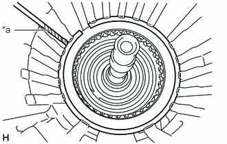
| *a | Protective Tape |
Using a screwdriver, remove the snap ring from the automatic transmission case sub-assembly.
- NOTICE:
-
Be careful not to damage the automatic transmission case sub-assembly.
- HINT:
-
Tape the screwdriver tip before use.
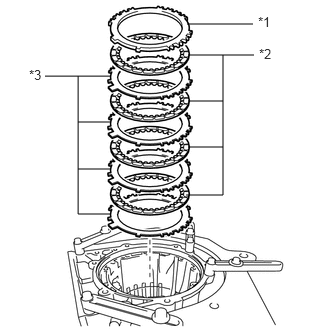
| *1 | No. 1 Brake Flange |
| *2 | No. 1 Brake Disc |
| *3 | No. 1 Brake Plate |
Remove the No. 1 brake flange, 4 No. 1 brake discs and 4 No. 1 brake plates from the automatic transmission case sub-assembly.
35681A
68.INSPECT NO. 1 BRAKE DISC
35698
69.REMOVE NO. 1 BRAKE CYLINDER WITH NO. 1 BRAKE PISTON
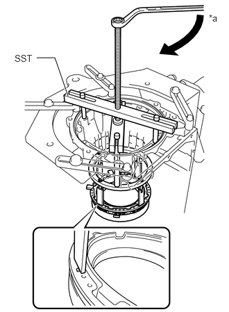
| *a | Turn |
Place SST on the No. 1 brake piston return spring sub-assembly, and compress the No. 1 brake piston return spring sub-assembly with a press.
- SST
- 09380-60012 (09381-06010, 09381-06040, 09381-06050, 09381-06070, 09381-06090, 09381-06100, 09381-06110, 09381-06120)
Using a screwdriver, remove the snap ring from the automatic transmission case sub-assembly.
- NOTICE:
-
Be careful not to damage the automatic transmission case sub-assembly.
- HINT:
-
Tape the screwdriver tip before use.
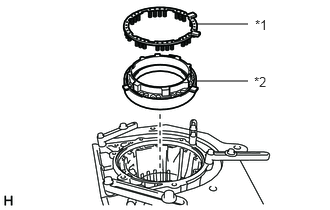
| *1 | No. 1 Brake Piston Return Spring Sub-assembly |
| *2 | No. 1 Brake Cylinder with No. 1 Brake Piston |
Remove the No. 1 brake piston return spring sub-assembly and No. 1 brake cylinder with No. 1 brake piston from the automatic transmission case sub-assembly.
35608J
70.INSPECT NO. 1 BRAKE PISTON RETURN SPRING SUB-ASSEMBLY
35621V
71.REMOVE NO. 1 BRAKE PISTON
While holding the No. 1 brake piston, apply compressed air to the oil hole of the No. 1 brake cylinder to remove the No. 1 brake piston from the No. 1 brake cylinder.
Remove the 2 O-rings from the No. 1 brake piston.
35684
72.INSPECT CLEARANCE OF NO. 4 BRAKE
35713
73.REMOVE INTERMEDIATE SHAFT WITH NO. 3 ONE-WAY CLUTCH ASSEMBLY AND REAR PLANETARY RING GEAR
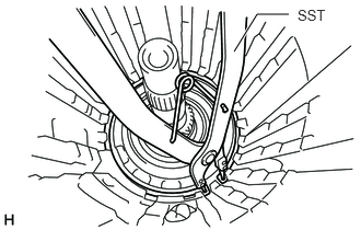
Using SST, remove the snap ring from the automatic transmission case sub-assembly.
- SST
- 09350-30020 (09350-07060)
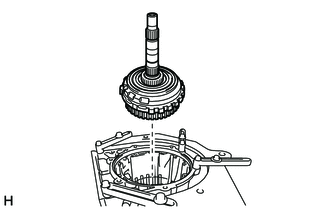
Remove the intermediate shaft with No. 3 one-way clutch assembly and rear planetary ring gear from the automatic transmission case sub-assembly.
35770C
74.INSPECT NO. 3 ONE-WAY CLUTCH ASSEMBLY
35770C
75.REMOVE NO. 3 ONE-WAY CLUTCH ASSEMBLY WITH ONE-WAY CLUTCH INNER RACE
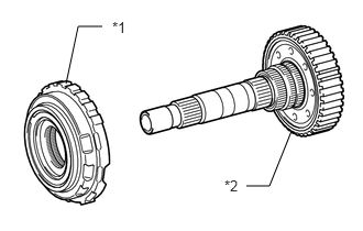
| *1 | No. 3 One-way Clutch Assembly with One-way Clutch Inner Race |
| *2 | Intermediate Shaft with Rear Planetary Ring Gear |
Remove the No. 3 one-way clutch assembly with one-way clutch inner race from the intermediate shaft with rear planetary ring gear.
35797B
76.REMOVE ONE-WAY CLUTCH INNER RACE
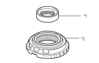
| *1 | One-way Clutch Inner Race |
| *2 | No. 3 One-way Clutch Assembly |
Remove the one-way clutch inner race from the No. 3 one-way clutch assembly.
35077D
77.REMOVE REAR PLANETARY RING GEAR FLANGE SUB-ASSEMBLY WITH REAR PLANETARY RING GEAR
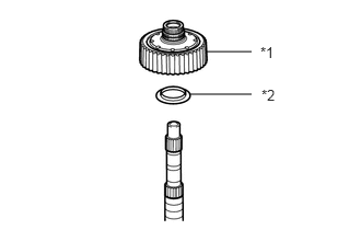
| *1 | Rear Planetary Ring Gear Flange Sub-assembly with Rear Planetary Ring Gear |
| *2 | Thrust Bearing Race |
Remove the rear planetary ring gear flange sub-assembly with rear planetary ring gear from the intermediate shaft.
Remove the thrust bearing race from the rear planetary ring gear flange sub-assembly with rear planetary ring gear.
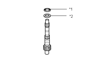
| *1 | Thrust Needle Roller Bearing |
| *2 | Thrust Bearing Race |
Remove the thrust needle roller bearing and thrust bearing race from the intermediate shaft.
35077D
78.INSPECT REAR PLANETARY RING GEAR FLANGE SUB-ASSEMBLY
35713
79.INSPECT INTERMEDIATE SHAFT
35761
80.REMOVE REAR PLANETARY RING GEAR
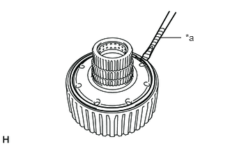
| *a | Protective Tape |
Using a screwdriver, remove the snap ring from the rear planetary ring gear flange sub-assembly with rear planetary ring gear.
- NOTICE:
-
Be careful not to damage the rear planetary ring gear flange sub-assembly with rear planetary ring gear.
- HINT:
-
Tape the screwdriver tip before use.
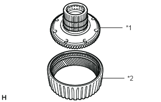
| *1 | Rear Planetary Ring Gear Flange Sub-assembly |
| *2 | Rear Planetary Ring Gear |
Remove the rear planetary ring gear from the rear planetary ring gear flange sub-assembly.
35760
81.REMOVE REAR PLANETARY GEAR ASSEMBLY WITH NO. 4 BRAKE DISC
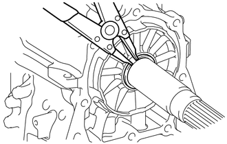
Using a snap ring expander, remove the snap ring from the output shaft of the rear planetary gear assembly.
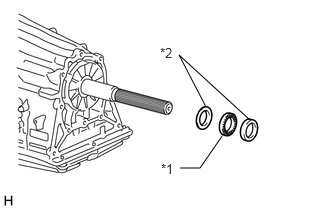
| *1 | Thrust Needle Roller Bearing |
| *2 | Thrust Bearing Race |
Remove the 2 thrust bearing races and thrust needle roller bearing from the output shaft of the rear planetary gear assembly.
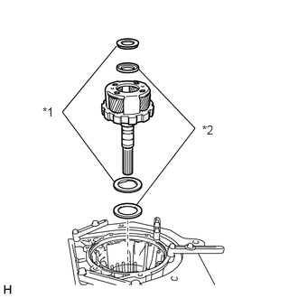
| *1 | Thrust Needle Roller Bearing |
| *2 | Thrust Bearing Race |
Remove the rear planetary gear assembly with No.4 brake disc from the automatic transmission case sub-assembly.
Remove the 2 thrust needle roller bearings and thrust bearing race from the rear planetary gear assembly with No. 4 brake disc.
Remove the thrust bearing race from the automatic transmission case sub-assembly.
35760
82.INSPECT REAR PLANETARY GEAR ASSEMBLY
35684
83.REMOVE NO. 4 BRAKE DISC
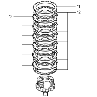
| *1 | No. 4 Brake Flange |
| *2 | No. 4 Brake Disc |
| *3 | No. 4 Brake Plate |
Remove the No. 4 brake flange, 7 No. 4 brake discs and 6 No. 4 brake plates from the rear planetary gear assembly.
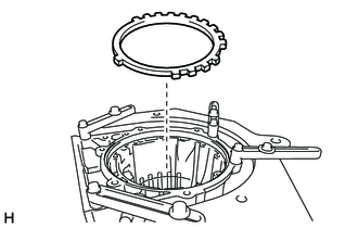
Remove the No. 4 brake flange from the automatic transmission case sub-assembly.
35684
84.INSPECT NO. 4 BRAKE DISC
35623H
85.REMOVE 1ST AND REVERSE BRAKE PISTON
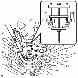
Place SST on the 1st and reverse brake return spring sub-assembly and compress the 1st and reverse brake return spring sub-assembly.
- SST
- 09380-60012 (09381-05040, 09381-05050, 09381-06030, 09381-06040, 09381-06080, 09381-06120, 09381-06130, 09381-06140)
Using SST, remove the snap ring from the automatic transmission case sub-assembly.
- SST
- 09350-30020 (09350-07070)
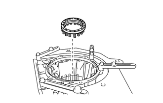
Remove the 1st and reverse brake return spring sub-assembly from the automatic transmission case sub-assembly.
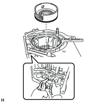
Apply compressed air to the oil hole of the automatic transmission case sub-assembly to remove the 1st and reverse brake piston from the automatic transmission case sub-assembly.
Remove the O-ring from the 1st and reverse brake piston.
35068
86.INSPECT 1ST AND REVERSE BRAKE RETURN SPRING SUB-ASSEMBLY
35626
87.REMOVE BRAKE REACTION SLEEVE
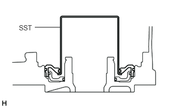
Using SST, remove the brake reaction sleeve from the automatic transmission case sub-assembly.
- SST
- 09350-30020 (09350-07080)
Remove the 2 O-rings from the brake reaction sleeve.
35629A
88.REMOVE NO. 4 BRAKE PISTON
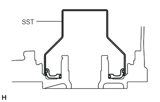
Using SST, remove the No. 4 brake piston from the automatic transmission case sub-assembly.
- SST
- 09350-30020 (09350-07090)
Remove the 2 O-rings from the No. 4 brake piston.
35639B
89.REMOVE BRAKE PLATE STOPPER SPRING
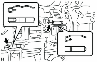
Remove the 2 brake plate stopper springs from the automatic transmission case sub-assembly.