AC60E AUTOMATIC TRANSMISSION / TRANSAXLE OIL COOLER(for 7GR-FKS) REMOVAL
CAUTION / NOTICE / HINT
The necessary procedures (adjustment, calibration, initialization, or registration) that must be performed after parts are removed, installed, or replaced during the oil cooler removal/installation are shown below.
| Replaced Part or Performed Procedure | Necessary Procedure | Effect/Inoperative Function when Necessary Procedures are not Performed | Link |
|---|---|---|---|
| Exhaust system parts | Inspection after repair | ·
Poor idle, etc. ·
Engine start function, etc. |
( 201902,999999,_51,_078720,_0381907,RM100000001G2VV,) 201902,999999,_51,_078720,_0381907,RM100000001G2VV,)
|
PROCEDURE

 17140
1.REMOVE EXHAUST MANIFOLD ASSEMBLY RH
17140
1.REMOVE EXHAUST MANIFOLD ASSEMBLY RH
2.DRAIN AUTOMATIC TRANSMISSION FLUID
32941
3.REMOVE NO. 1 OIL COOLER INLET HOSE AND NO. 1 OIL COOLER OUTLET HOSE
- NOTICE:
-
When disconnecting the hoses from the tube, support the tube by hand and be careful to prevent the tube from being deformed.
- HINT:
-
Use a container to catch any ATF.

| *1 | No. 1 Oil Cooler Inlet Hose |
| *2 | No. 1 Oil Cooler Outlet Hose |
Slide the 2 clips and disconnect the No. 1 oil cooler inlet hose and No. 1 oil cooler outlet hose from the No. 1 oil cooler inlet tube and No. 1 oil cooler outlet tube.
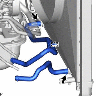
Disconnect the hose clamp from the fan shroud.
Slide the 2 clips and remove the No. 1 oil cooler inlet hose and No. 1 oil cooler outlet hose from the radiator assembly.
32921
4.REMOVE NO. 1 OIL COOLER INLET TUBE AND NO. 1 OIL COOLER OUTLET TUBE
- HINT:
-
Use a container to catch any ATF.
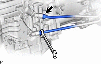
Disconnect the No. 1 oil cooler inlet tube and No. 1 oil cooler outlet tube from the automatic transmission assembly.
Remove the 3 bolts to open the No. 1 automatic transmission oil cooler tube clamp and 2 transmission oil cooler tube clamp sub-assemblies and remove the No. 1 oil cooler inlet tube and No. 1 oil cooler outlet tube.
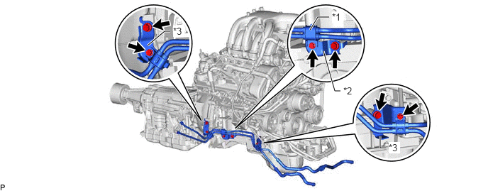
| *1 | No. 1 Automatic Transmission Oil Cooler Tube Clamp | *2 | No. 2 Oil Cooler Tube Clamp |
| *3 | Transmission Oil Cooler Tube Clamp Sub-assembly | - | - |
Remove the 3 bolts, No. 2 oil cooler tube clamp and 2 transmission oil cooler tube clamp sub-assemblies from the automatic transmission assembly and engine assembly.