7GR-FKS ENGINE MECHANICAL CYLINDER BLOCK INSPECTION
PROCEDURE

 1.INSPECT CYLINDER BLOCK FOR WARPAGE
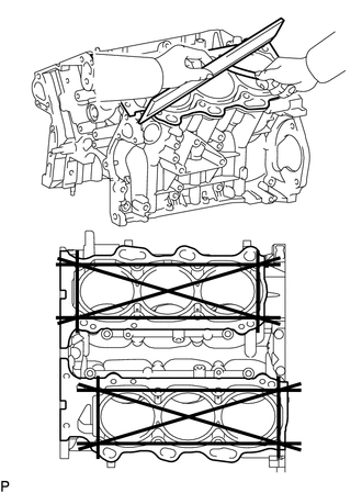
Using a precision straightedge and feeler gauge, measure the warpage of the contact surface of the cylinder head gasket.
- Maximum warpage:
0.07 mm (0.00276 in.)
- HINT:
-
If the warpage is more than the maximum, replace the cylinder block sub-assembly.
2.INSPECT CYLINDER BORE
Visually check the cylinder for vertical scratches.
If necessary, replace the cylinder block sub-assembly.
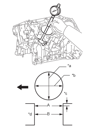
| *a | Thrust Direction |
| *b | Axial Direction |
| *c | 10 mm (0.394 in.) |
| *d | Center |

|
Engine Front |
Using a cylinder gauge, measure the cylinder bore diameter at positions A and B in the thrust and axial directions.
- Reference value (New parts):
94.000 to 94.012 mm (3.70078 to 3.70125 in.)
- Maximum diameter:
94.200 mm (3.7087 in.)
- HINT:
-
If the average diameter of 4 positions is more than the maximum, replace the cylinder block sub-assembly.
13101
3.INSPECT PISTON SUB-ASSEMBLY WITH PIN
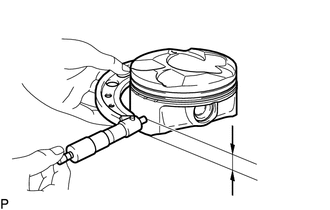
Using a micrometer, measure the piston diameter at right angles to the piston center line where the distance from the piston end is as specified.
- Distance:
9.2 mm (0.362 in.)
- Reference value (New parts):
93.962 to 93.992 mm (3.69928 to 3.70047 in.)
- Minimum diameter:
93.830 mm (3.69409 in.)
- HINT:
-
If the piston diameter is less than the minimum, replace the piston and piston pin as a set.
4.INSPECT PISTON OIL CLEARANCE
Measure the cylinder bore diameter in the thrust directions.
Subtract the piston diameter measurement from the cylinder bore diameter measurement.
- Reference value (New parts):
0.008 to 0.050 mm (0.000315 to 0.00197 in.)
- Maximum oil clearance:
0.075 mm (0.00295 in.)
If the oil clearance is more than the maximum, replace all the pistons. If necessary, replace the cylinder block sub-assembly.
5.INSPECT RING GROOVE CLEARANCE
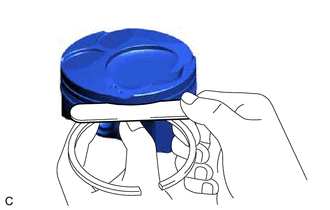
Using a feeler gauge, measure the clearance between a new piston ring and the wall of the ring groove.
- Standard Ring Groove Clearance:
Item Specified Condition No. 1 compression ring 0.020 to 0.070 mm (0.000787 to 0.00276 in.) No. 2 compression ring 0.020 to 0.060 mm (0.000787 to 0.00236 in.) Oil ring 0.070 to 0.150 mm (0.00276 to 0.00591 in.)
- HINT:
-
If the clearance is not as specified, replace the piston.
6.INSPECT PISTON PIN OIL CLEARANCE
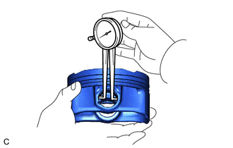
Using a caliper gauge, measure the inside diameter of the piston pin hole.
- Standard Piston Pin Hole Inside Diameter:
Mark Specified Condition A 21.998 to 22.001 mm (0.8661 to 0.8662 in.) B 22.001 to 22.004 mm (0.8662 to 0.8663 in.) C 22.004 to 22.007 mm (0.8663 to 0.8664 in.)
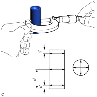
| *a | 5.0 mm (0.197 in.) |
| *b | 28 mm (1.10 in.) |
Using a micrometer, measure the piston pin diameter.
- Standard Piston Pin Diameter:
Mark Specified Condition A 21.997 to 22.000 mm (0.86602 to 0.86614 in.) B 22.001 to 22.003 mm (0.86618 to 0.86626 in.) C 22.004 to 22.006 mm (0.86630 to 0.86638 in.)
Subtract the piston pin diameter measurement from the piston pin hole diameter measurement.
- Standard oil clearance:
-0.002 to 0.004 mm (-0.0000787 to 0.000158 in.)
- Maximum oil clearance:
0.015 mm (0.000591 in.)
- HINT:
-
If the oil clearance is more than the maximum, replace the piston and piston pin as a set.
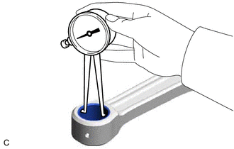
Using a caliper gauge, measure the inside diameter of the connecting rod small end bush.
- Standard Bushing Inside Diameter:
Mark Specified Condition A 22.005 to 22.008 mm (0.86634 to 0.86645 in.) B 22.009 to 22.011 mm (0.86649 to 0.86657 in.) C 22.012 to 22.014 mm (0.86661 to 0.86669 in.)
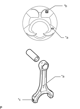
| *a | Front Mark |
| *b | Piston Pin Hole Inside Diameter Mark |
| *c | Connecting Rod Bushing Inside Diameter Mark |
Subtract the piston pin diameter measurement from the bushing inside diameter measurement.
- Standard oil clearance:
0.005 to 0.011 mm (0.000197 to 0.000433 in.)
- Maximum oil clearance:
0.030 mm (0.00118 in.)
- HINT:
- ·
If the oil clearance is more than the maximum, replace the connecting rod small end bush.
·If necessary, replace the connecting rod sub-assembly and piston sub-assembly with pin.
7.INSPECT CRANKSHAFT THRUST CLEARANCE
Install the crankshaft bearing cap.
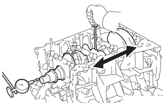
Using a dial indicator, measure the thrust clearance while prying the crankshaft back and forth with a screwdriver.
- Standard thrust clearance:
0.04 to 0.24 mm (0.00157 to 0.00945 in.)
- Maximum thrust clearance:
0.30 mm (0.0118 in.)
- Thrust washer thickness:
2.43 to 2.48 mm (0.0957 to 0.0976 in.)
- HINT:
-
If the thrust clearance is more than the maximum, replace the crankshaft thrust washer set. If necessary, replace the crankshaft.
8.INSPECT PISTON RING END GAP
Insert the piston ring into the cylinder bore.
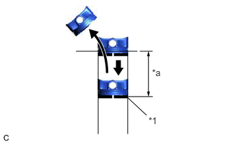
| *1 | Piston Ring |
| *a | 110 mm |
Using a piston, push the piston ring slightly beyond the bottom of the ring travel, 110 mm (4.33 in.) from the top of the cylinder block sub-assembly.
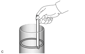
Using a feeler gauge, measure the end gap.
- Standard End Gap:
Item Specified Condition No. 1 0.22 to 0.27 mm (0.00866 to 0.0106 in.) No. 2 0.70 to 0.75 mm (0.0276 to 0.0295 in.) Oil 0.10 to 0.35 mm (0.00394 to 0.0138 in.)
- Maximum End Gap:
Item Specified Condition No. 1 0.50 mm (0.0197 in.) No. 2 0.85 mm (0.0335 in.) Oil 0.45 mm (0.0177 in.)
If the end gap is more than the maximum, replace the piston ring. If the end gap is more than the maximum even with a new piston ring, replace the cylinder block sub-assembly.
9.INSPECT CONNECTING ROD SUB-ASSEMBLY
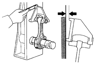
Using a rod aligner and feeler gauge, check the connecting rod alignment.
Check for out-of-alignment.
- Maximum out-of-alignment:
0.05 mm (0.00197 in.) per 100 mm (3.94 in.)
If the out-of-alignment is more than the maximum, replace the connecting rod sub-assembly.
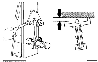
Check for twist.
- Maximum twist:
0.15 mm (0.00591 in.) per 100 mm (3.94 in.)
If the twist is more than the maximum, replace the connecting rod sub-assembly.
13265
10.INSPECT CONNECTING ROD BOLT
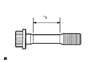
| *a | Measurement Area |
Using a vernier caliper, measure the diameter of the bolt at several points within the area shown in the illustration.
- Standard diameter:
7.2 to 7.3 mm (0.283 to 0.287 in.)
- Minimum diameter:
7.0 mm (0.276 in.)
If the diameter is less than the minimum, replace the bolt.
- HINT:
- ·
Diameter measurements should be done at several points.
- ·
If the diameter is less than the minimum, replace the connecting rod bolt with a new one. Failure to do so may lead to engine damage.
- ·
If there is any thread deformation, replace the connecting rod bolt with a new one.
13411
11.INSPECT CRANKSHAFT
Inspect runout.
Clean the crank journal.
Place the crankshaft on V-blocks.
Using a dial indicator, measure the runout at the center journal.
- Maximum runout:
0.06 mm (0.00236 in.)
- HINT:
-
If the runout is more than the maximum, replace the crankshaft.
Inspect the main journals.
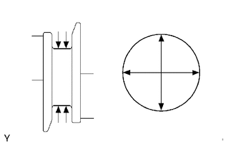
Using a micrometer, measure the diameter of each main journal.
- Standard journal diameter:
60.988 to 61.000 mm (2.40110 to 2.40157 in.)
- HINT:
-
If the diameter is not as specified, check the oil clearance. If necessary, replace the crankshaft.
Check each main journal for taper and out-of-round as shown in the illustration.
- Maximum taper and out-of-round:
0.02 mm (0.000787 in.)
- HINT:
-
If the taper or out-of-round is more than the maximum, replace the crankshaft.
Inspect the crank pins.
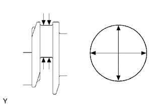
Using a micrometer, measure the diameter of each crank pin.
- Standard crank pin diameter:
52.992 to 53.000 mm (2.08630 to 2.08661 in.)
- HINT:
-
If the diameter is not as specified, check the oil clearance. If necessary, replace the crankshaft.
Check each crank pin for taper and out-of-round as shown in the illustration.
- Maximum taper and out-of-round:
0.02 mm (0.000787 in.)
- HINT:
-
If the taper or out-of-round is more than the maximum, replace the crankshaft.
12.INSPECT CRANKSHAFT OIL CLEARANCE
Check the crank journal and crankshaft bearing for pitting and scratches.
Install the crankshaft bearing.
Place the crankshaft on the cylinder block.
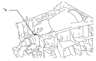
| *a | Plastigage |
Lay a strip of Plastigage across each journal.
Examine the front marks and numbers to install the crankshaft bearing caps on the cylinder block.
- HINT:
-
A number is marked on each main bearing cap to indicate the installation position.
Install the crankshaft bearing caps.
- NOTICE:
-
Do not turn the crankshaft.
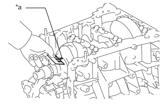
| *a | Plastigage |
Measure the Plastigage at its widest point.
- Standard Oil Clearance:
Item Specified Condition No. 1, No. 4 Journal 0.019 to 0.029 mm (0.000748 to 0.00114 in.) No. 2, No. 3 Journal 0.025 to 0.035 mm (0.000984 to 0.00138 in.)
- Maximum Oil Clearance:
Item Specified Condition No. 1, No. 4 Journal 0.050 mm (0.00197 in.) No. 2, No. 3 Journal 0.060 mm (0.00236 in.)
- NOTICE:
-
Completely remove the Plastigage after the measurement.
- HINT:
-
If the oil clearance is more than the maximum, replace the crankshaft bearings. If necessary, replace the crankshaft.
If replacing a bearing, replace it with one having the same number. If the number of the bearing cannot be determined, select the correct bearing by adding together the numbers imprinted on the cylinder block and crankshaft, and then refer to the table below for the appropriate bearing number. There are 5 sizes of standard bearings, marked "1", "2", "3", "4" and "5" accordingly.
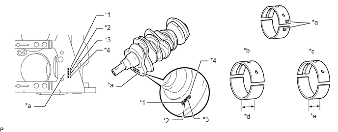
| *1 | No. 1 | *2 | No. 2 |
| *3 | No. 3 | *4 | No. 4 |
| *a | Number Mark | *b | No. 1 and No. 4 Journal Bearing |
| *c | No. 2 and No. 3 Journal Bearing | *d | 21 mm (0.827 in.) |
| *e | 18 mm (0.709 in.) | - | - |
- Crankshaft Bearings:
Cylinder block sub-assembly+ Crankshaft Upper crankshaft bearing to be used Lower crankshaft bearing to be used 0 to 3 "1" "1" 4 to 6 "1" "2" 7 to 9 "2" "2" 10 to 12 "2" "3" 13 to 15 "3" "3" 16 to 18 "3" "4" 19 to 21 "4" "4" 22 to 24 "4" "5" 25 to 28 "5" "5"
- HINT:
-
EXAMPLE: Cylinder block sub-assembly "12" + Crankshaft "06" = Total number 18 (Use upper bearing "3" and lower bearing "4")
- Crankshaft Main Journal Diameter:
Mark Specified Condition "00" 60.999 to 61.000 mm (2.40153 to 2.40157 in.) "01" 60.998 to 60.999 mm (2.40149 to 2.40153 in.) "02" 60.997 to 60.998 mm (2.40145 to 2.40149 in.) "03" 60.996 to 60.997 mm (2.40141 to 2.40145 in.) "04" 60.995 to 60.996 mm (2.40137 to 2.40141 in.) "05" 60.994 to 60.995 mm (2.40133 to 2.40137 in.) "06" 60.993 to 60.994 mm (2.40129 to 2.40133 in.) "07" 60.992 to 60.993 mm (2.40126 to 2.40129 in.) "08" 60.991 to 60.992 mm (2.40122 to 2.40126 in.) "09" 60.990 to 60.991 mm (2.40118 to 2.40122 in.) "10" 60.989 to 60.990 mm (2.40114 to 2.40118 in.) "11" 60.988 to 60.989 mm (2.40110 to 2.40114 in.)
- Standard Upper Crankshaft Bearing Center Wall Thickness (No. 1 and No. 4 journal):
Mark Specified Condition "1" 2.497 to 2.500 mm (0.09831 to 0.09843 in.) "2" 2.501 to 2.503 mm (0.09846 to 0.09854 in.) "3" 2.504 to 2.506 mm (0.09858 to 0.09866 in.) "4" 2.507 to 2.509 mm (0.09870 to 0.09878 in.) "5" 2.510 to 2.512 mm (0.09882 to 0.09890 in.)
- Standard Lower Crankshaft Bearing Center Wall Thickness (No. 1 and No. 4 journal):
Mark Specified Condition "1" 2.478 to 2.481 mm (0.09756 to 0.09768 in.) "2" 2.482 to 2.484 mm (0.09772 to 0.09780 in.) "3" 2.485 to 2.487 mm (0.09783 to 0.09791 in.) "4" 2.488 to 2.490 mm (0.09795 to 0.09803 in.) "5" 2.491 to 2.493 mm (0.09807 to 0.09815 in.)
- Standard Upper Crankshaft Bearing Center Wall Thickness (No. 2 and No. 3 journal):
Mark Specified Condition "1" 2.476 to 2.479 mm (0.09748 to 0.09760 in.) "2" 2.480 to 2.482 mm (0.09764 to 0.09772 in.) "3" 2.483 to 2.485 mm (0.09776 to 0.09783 in.) "4" 2.486 to 2.488 mm (0.09787 to 0.09795 in.) "5" 2.489 to 2.491 mm (0.09799 to 0.09807 in.)
- Standard Lower Crankshaft Bearing Center Wall Thickness (No. 2 and No. 3 journal):
Mark Specified Condition "1" 2.493 to 2.496 mm (0.09815 to 0.09827 in.) "2" 2.497 to 2.499 mm (0.09831 to 0.09839 in.) "3" 2.500 to 2.502 mm (0.09843 to 0.09850 in.) "4" 2.503 to 2.505 mm (0.09854 to 0.09862 in.) "5" 2.506 to 2.508 mm (0.09866 to 0.09874 in.)
11416
13.INSPECT CRANKSHAFT BEARING CAP SET BOLT
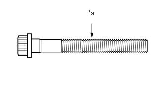
| *a | Measurement Point |
Using a vernier caliper, measure the diameter of the threads at the measurement point.
- Standard diameter:
10.8 to 11.0 mm (0.4252 to 0.4331 in.)
- Minimum diameter:
10.7 mm (0.4213 in.)
- Measurement point (distance from the seat):
47 mm (1.85 in.)
- HINT:
- ·
If the diameter is less than the minimum, replace the crankshaft bearing cap set bolt. Failure to do so may lead to engine damage.
- ·
If there is any thread deformation, replace the crankshaft bearing cap set bolt with a new one.
15708
14.INSPECT NO. 1 OIL NOZZLE SUB-ASSEMBLY
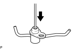
Push the check valve with a pin to check if it is stuck.
- HINT:
-
If the check valve is stuck, replace the No. 1 oil nozzle.
Push the check valve with a pin to check if it moves smoothly.
If the check valve does not move smoothly, clean or replace the No. 1 oil nozzle sub-assembly.
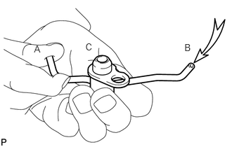
While covering A, blow air into B. Check that air does not leak through C. Perform the check again while covering B and blowing air into A.
If air leaks, clean or replace the No. 1 oil nozzle sub-assembly.
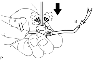
Push the check valve while covering A, and blow air into B. Check that air passes through C. Perform the check again while covering B, pushing the check valve and blowing air into A.
If air does not pass through C, clean or replace the No. 1 oil nozzle sub-assembly.