7GR-FKS ENGINE MECHANICAL ENGINE UNIT DISASSEMBLY
PROCEDURE

 12185
1.REMOVE OIL FILLER CAP HOUSING
12185
1.REMOVE OIL FILLER CAP HOUSING
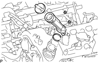
Remove the oil filler cap sub-assembly.
Remove the 2 nuts, oil filler cap housing assembly and gasket.
19100P
2.REMOVE SPARK PLUG
12101A
3.REMOVE OIL PAN DRAIN PLUG
Remove the oil pan drain plug and gasket.
12601B
4.REMOVE NO. 1 ENGINE COVER SUB-ASSEMBLY (w/o Secondary Air Injection System)
12601B
5.REMOVE NO. 1 ENGINE COVER SUB-ASSEMBLY (w/o Secondary Air Injection System)

Remove the 2 clips and No. 1 engine cover sub-assembly.
12204
6.REMOVE PCV VALVE SUB-ASSEMBLY
15370B
7.REMOVE CAMSHAFT TIMING OIL CONTROL SOLENOID ASSEMBLY (for Intake Side of Bank 1)
15370B
8.REMOVE CAMSHAFT TIMING OIL CONTROL SOLENOID ASSEMBLY (for Exhaust Side of Bank 1)
15370C
9.REMOVE CAMSHAFT TIMING OIL CONTROL SOLENOID ASSEMBLY (for Intake Side of Bank 2)
15370C
10.REMOVE CAMSHAFT TIMING OIL CONTROL SOLENOID ASSEMBLY (for Exhaust Side of Bank 2)
11.REMOVE VVT SENSOR (for Intake Side of Bank 1)
12.REMOVE VVT SENSOR (for Exhaust Side of Bank 1)
13.REMOVE VVT SENSOR (for Intake Side of Bank 2)
14.REMOVE VVT SENSOR (for Exhaust Side of Bank 2)
11401G
15.REMOVE CRANKSHAFT POSITION SENSOR
11415
16.REMOVE CYLINDER BLOCK WATER DRAIN COCK SUB-ASSEMBLY
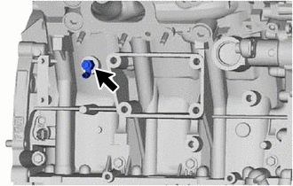
Remove the cylinder block water drain cock plug from the cylinder block water drain cock sub-assembly.
Remove the water cylinder block water drain cock sub-assembly from the cylinder block sub-assembly.
17.REMOVE OIL FILTER ELEMENT
15609
18.REMOVE OIL FILTER BRACKET SUB-ASSEMBLY
15710
19.REMOVE OIL COOLER ASSEMBLY
13471
20.REMOVE CRANKSHAFT PULLEY
16031
21.REMOVE WATER INLET SUB-ASSEMBLY WITH THERMOSTAT
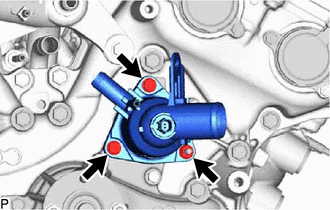
Remove the 2 bolts, nut, water inlet sub-assembly with thermostat and gasket.
16331
22.REMOVE WATER OUTLET
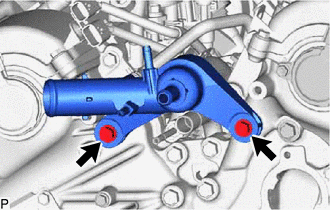
Remove the 2 bolts and water outlet.
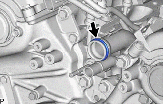
Remove the O-ring.
16356
23.REMOVE REAR WATER BY-PASS JOINT
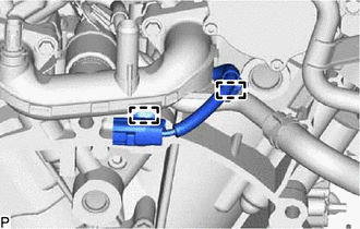
Detach the 2 clamps and disconnect the No. 5 engine wire.
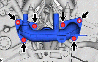
Remove the 4 bolts, 2 nuts and rear water by-pass joint.
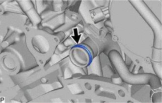
Remove the O-ring from the No. 1 water outlet pipe.
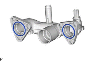
Remove the 2 O-rings from the rear water by-pass joint.
24.REMOVE FUEL PUMP SPACER GASKET
Remove the fuel pump spacer gasket from the cylinder head cover sub-assembly.
11201
25.REMOVE CYLINDER HEAD COVER SUB-ASSEMBLY
11202
26.REMOVE CYLINDER HEAD COVER SUB-ASSEMBLY LH
27.REMOVE OIL FILLER STUD BOLT
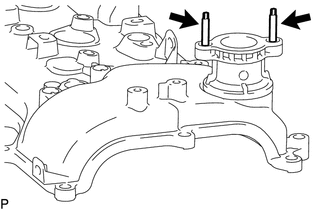
Remove the 2 oil filler stud bolts from the cylinder head cover sub-assembly LH.
11193
28.REMOVE SPARK PLUG TUBE GASKET
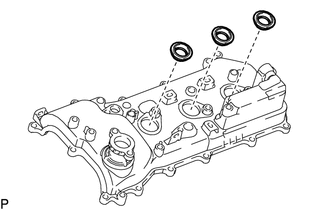
Remove the 6 spark plug tube gaskets.
- HINT:
-
Be careful not to damage the gasket when removing it as the removed gasket needs to be used when installing a new one.
12101A
29.REMOVE OIL PAN DRAIN PLUG
Remove the oil pan drain plug and gasket.
12102A
30.REMOVE NO. 2 OIL PAN SUB-ASSEMBLY
15104
31.REMOVE OIL STRAINER SUB-ASSEMBLY
89491
32.REMOVE ENGINE OIL LEVEL SENSOR
15367
33.REMOVE OIL LEVEL SENSOR BRACKET
12101
34.REMOVE OIL PAN SUB-ASSEMBLY
12121
35.REMOVE NO. 1 OIL PAN BAFFLE PLATE
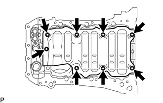
Remove the 8 bolts and No. 1 oil pan baffle plate.
11381
36.REMOVE REAR ENGINE OIL SEAL RETAINER
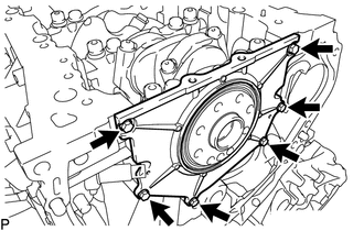
Remove the 6 bolts.
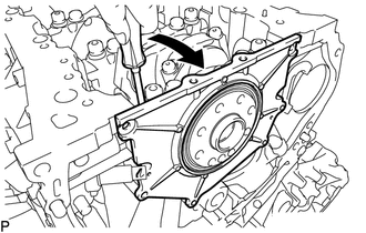

|
Pry |
Using a screwdriver, pry out the rear engine oil seal retainer.
- NOTICE:
-
Be careful not to damage the rear engine oil seal retainer.
- HINT:
-
Tape the screwdriver tip before use.
11381A
37.REMOVE REAR CRANKSHAFT OIL SEAL
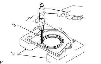
| *a | Wooden Block |
| *b | Protective Tape |
Place the rear engine oil seal retainer on wooden blocks.
- NOTICE:
-
Be careful not to damage the rear engine oil seal retainer.
Using a screwdriver and a hammer, tap out the rear crankshaft oil seal.
- HINT:
-
Tape the screwdriver tip before use.
11310
38.REMOVE TIMING CHAIN COVER ASSEMBLY
16100
39.REMOVE ENGINE WATER PUMP ASSEMBLY
11301C
40.REMOVE FRONT CRANKSHAFT OIL SEAL
41.SET NO. 1 CYLINDER TO TDC/COMPRESSION
Temporarily install the crankshaft pulley set bolt.
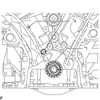
| *1 | Crankshaft Pulley Set Key |
| *a | Center Mark |
Set the crankshaft pulley set key to the RH block bore center mark (TDC/compression).
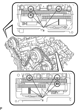
| *a | Timing Mark |
Check that the timing marks of the camshaft timing gears are aligned with the timing marks of the camshaft bearing cap as shown in the illustration.
If not, turn the crankshaft 1 revolution (360°) and align the timing marks as described above.
13540
42.REMOVE NO. 1 CHAIN TENSIONER ASSEMBLY
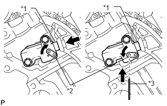
| *1 | Plunger |
| *2 | Stopper Plate |
| *3 | Pin |
Move the stopper plate upward to release the lock, and push the plunger deep into the tensioner.
Move the stopper plate downward to set the lock, and insert a pin of 1.27 mm (0.0500 in.) diameter into the hole of the stopper plate.
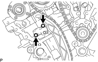
Remove the 2 bolts and No. 1 chain tensioner assembly.
13559
43.REMOVE CHAIN TENSIONER SLIPPER
Remove the chain tensioner slipper.
13506
44.REMOVE CHAIN SUB-ASSEMBLY
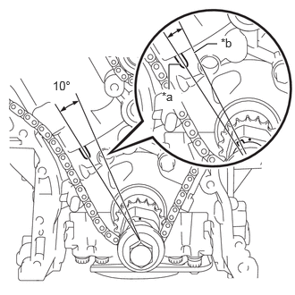
| *a | Timing Mark |
| *b | Center Line |
Turn the crankshaft counterclockwise 10° to loosen the chain of the crankshaft timing gear or sprocket.
Remove the crankshaft pulley set bolt.
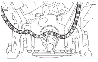
Remove the chain sub-assembly from the crankshaft timing gear or sprocket and place it on the crankshaft.
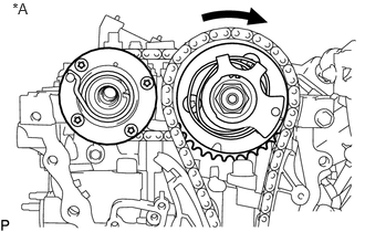
| *A | for Bank 1 |
Turn the camshaft timing gear assembly on bank 1 clockwise (approximately 60°) and set it as shown in the illustration. Be sure to loosen the chain sub-assembly between the banks.
Remove the chain sub-assembly.
13530
45.REMOVE IDLE SPROCKET ASSEMBLY
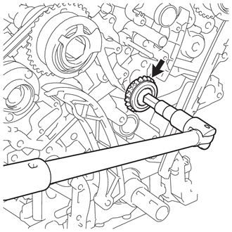
Using a 10 mm hexagon wrench, remove the No. 2 idle gear shaft, idle sprocket assembly and No. 1 idle gear shaft.
13561
46.REMOVE NO. 1 CHAIN VIBRATION DAMPER
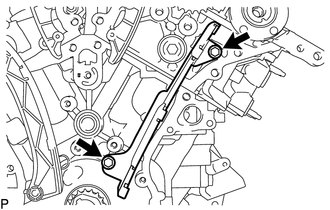
Remove the 2 bolts and No. 1 chain vibration damper.
13562
47.REMOVE NO. 2 CHAIN VIBRATION DAMPER
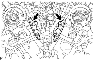
Remove the 2 No. 2 chain vibration dampers.
13521
48.REMOVE CRANKSHAFT TIMING GEAR OR SPROCKET
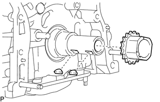
Remove the crankshaft timing gear or sprocket from the crankshaft.
Remove the 2 crankshaft timing gear keys from the crankshaft.
49.REMOVE CAMSHAFT TIMING GEARS AND NO. 2 CHAIN (for Bank 1)
13550
50.REMOVE NO. 2 CHAIN TENSIONER ASSEMBLY
51.REMOVE CAMSHAFT BEARING CAP (for Bank 1)
23476
52.REMOVE FUEL PUMP LIFTER HOUSING
13511
53.REMOVE CAMSHAFT
13512
54.REMOVE NO. 2 CAMSHAFT
11103C
55.REMOVE CAMSHAFT HOUSING SUB-ASSEMBLY RH
56.REMOVE CAMSHAFT TIMING GEARS AND NO. 2 CHAIN (for Bank 2)
13560A
57.REMOVE NO. 3 CHAIN TENSIONER ASSEMBLY
58.REMOVE CAMSHAFT BEARING CAP (for Bank 2)
13053
59.REMOVE NO. 3 CAMSHAFT SUB-ASSEMBLY
13054
60.REMOVE NO. 4 CAMSHAFT SUB-ASSEMBLY
11104A
61.REMOVE CAMSHAFT HOUSING SUB-ASSEMBLY LH
15678E
62.REMOVE OIL CONTROL VALVE FILTER LH
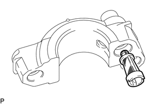
Remove the oil control valve filter LH from the camshaft bearing cap.
15678D
63.REMOVE OIL CONTROL VALVE FILTER RH
Remove the oil control valve filter RH from the camshaft bearing cap.
11159F
64.REMOVE CAMSHAFT BEARING CAP OIL HOLE GASKET
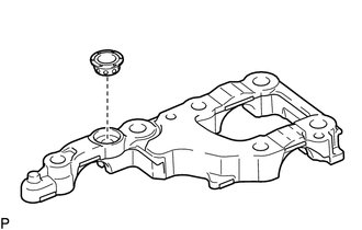
Remove the camshaft bearing cap oil hole gasket from the No. 6 camshaft bearing cap.
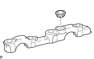
Remove the camshaft bearing cap oil hole gasket from the No. 7 camshaft bearing cap.
13801
65.REMOVE NO. 1 VALVE ROCKER ARM SUB-ASSEMBLY
13750
66.REMOVE VALVE LASH ADJUSTER ASSEMBLY
13716
67.REMOVE VALVE STEM CAP
11101
68.REMOVE CYLINDER HEAD SUB-ASSEMBLY
11115
69.REMOVE CYLINDER HEAD GASKET
11102
70.REMOVE CYLINDER HEAD LH
11116
71.REMOVE NO. 2 CYLINDER HEAD GASKET
82125N
72.REMOVE NO. 5 ENGINE WIRE
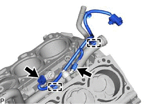
Disconnect the 2 connectors.
Detach the 2 clamps and remove the No. 5 engine wire.
89615
73.REMOVE KNOCK CONTROL SENSOR
16332
74.REMOVE NO. 1 WATER OUTLET PIPE
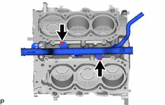
Remove the 2 bolts and No. 1 water outlet pipe.
75.REMOVE CYLINDER BLOCK WATER JACKET SPACER
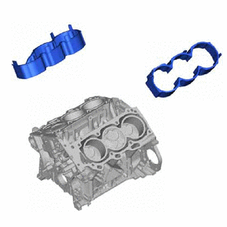
Remove the 2 cylinder block water jacket spacers from the cylinder block sub-assembly.
- NOTICE:
-
Be sure to remove the water jacket spacers. If not, they may fall and become damaged when the cylinder block sub-assembly is inverted.
11114A
76.REMOVE STRAIGHT PIN
- NOTICE:
-
It is not necessary to remove a straight pin unless it is being replaced.
11151
77.REMOVE RING PIN
- NOTICE:
-
It is not necessary to remove a ring pin unless it is being replaced.