EXTERIOR PANELS / TRIM SIDE MUDGUARD(for Wagon) REASSEMBLY
CAUTION / NOTICE / HINT
- HINT:
- ·
Use the same procedure for the RH and LH sides.
·The procedure listed below is for the LH side.
·A bolt without a torque specification is shown in the standard bolt chart.
PROCEDURE

 1.INSTALL FRONT SIDE PANEL RETAINER
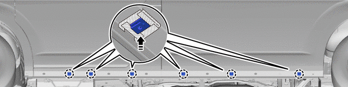
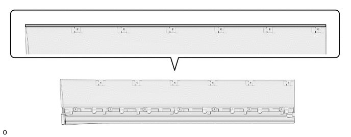
w/ No. 1 Side Mudguard Protector LH:
Attach the claw and install the 6 front side panel retainers.

|
Install in this Direction | - | - |
Remove the protective tape.
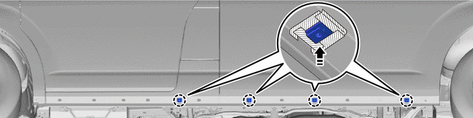
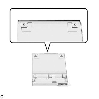
w/o No. 1 Side Mudguard Protector LH:
Attach the claw and install the 4 front side panel retainers.
|
|
Install in this Direction | - | - |
Remove the protective tape.
53824C
2.INSTALL FRONT NO. 2 SIDE PANEL PROTECTOR LH
|
|
Install in this Direction |
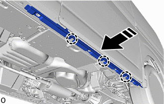
Attach the claw and install the front No. 2 side panel protector LH as shown in the illustration.
Install a new grommet.
Install 4 new retainers.
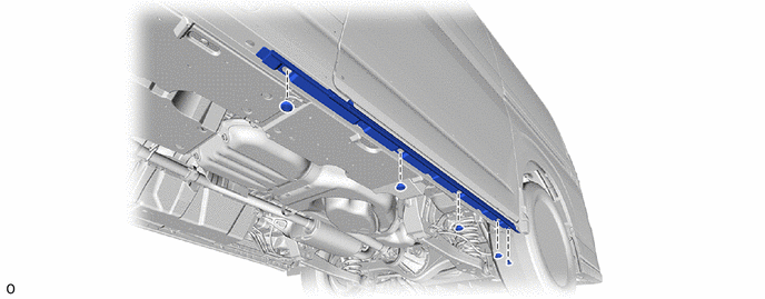
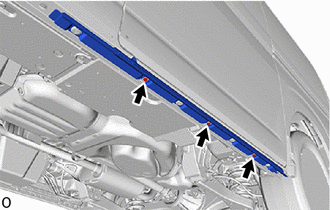
Install the 3 screws.
65632D
3.INSTALL REAR FRONT WHEEL HOUSE PLATE LH
53822G
4.INSTALL FRONT NO. 1 SIDE PANEL PROTECTOR LH (w/o Front No. 1 Side Panel Protector LH)
|
|
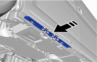
Install in this Direction |
Attach the claw and install the front No. 1 side panel protector LH as shown in the illustration.
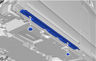
Install 2 new retainers.
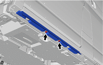
Install the 2 screws.
75652D
5.INSTALL QUARTER OUTSIDE MOULDING LH
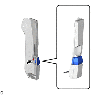
Install the quarter outside moulding LH with the screw.
76922J
6.INSTALL NO. 2 SIDE MUDGUARD PROTECTOR
- HINT:
-
When installing the No. 2 side mudguard protector, heat the quarter panel mudguard sub-assembly LH using a heat light.
- Standard Value:
Part Temperature Quarter Panel Mudguard Sub-assembly LH 20 to 30°C (68 to 86°F)
- CAUTION:
-
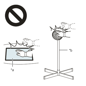 2.365,2 2.698,2 false 0.5,2.333 0.5,2.667 true 0.427,2.708 0.74,2.865 0.313,0.156 10 false *a 2.76,1.927 3.073,2.083 0.313,0.156 10 false *b
*a Heated Part *b Heat Light
- ·
Do not touch the heat light and heated parts.
·Touching the heat light may result in burns.
·Touching heated parts for a long time may result in burns.
When reusing the quarter panel mudguard sub-assembly LH:
Using a heat light, heat the quarter panel mudguard sub-assembly LH surface.
Remove any remaining double-sided tape from the quarter panel mudguard sub-assembly LH.
Wipe off any tape adhesive residue with cleaner.
- NOTICE:
- ·
Installing the No. 2 side mudguard protector with some double-sided tape remaining may cause poor adhesion. Perform this procedure until the tape is sufficiently removed.
·Make sure to use a cloth when removing. Using a screwdriver, etc., may cause damage and poor adhesion.
·Also, clean a new quarter panel mudguard sub-assembly LH surface.
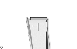
| *a | Scribed Line |

|
Primer Application |
Apply primer to the quarter panel mudguard sub-assembly LH on the installation area of the No. 2 side mudguard protector using a brush or felt.
- NOTICE:
- ·
Replace the brush or felt if it is dirty or has become hardened.
·Keep any painted surface free from primer.
·If the primer contacts a painted surface, it may leave light primer marks. Therefore, use protective tape when using liquid primer.
·Do not touch surfaces to which primer has been applied until the No. 2 side mudguard protector has been attached.
Let the primer dry sufficiently.
- NOTICE:
-
Do not touch applied surfaces until the primer is dry.
- Recommended drying time:
10 minutes or more (at 23°C (73°F))
Remove the release paper of a new No. 2 side mudguard protector trying not to touch the adhesional surface.
- HINT:
-
After removing the release paper, keep the exposed adhesive free from foreign matter.

| *a | Scribed Line |
Install the No. 2 side mudguard protector as shown in the illustration.
- Standard Value:
Area Dimensions B 0 to 2.0 mm (0 to 0.0787 in.)
- HINT:
-
Press the No. 2 side mudguard protector firmly to install it.
76934A
7.INSTALL NO. 2 SIDE MUDGUARD BRACKET LH
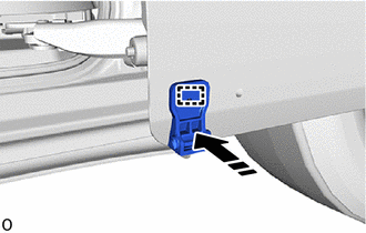
|
|
Install in this Direction |
Attach the guide and install the No. 2 side mudguard bracket LH.
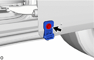
Install the screw.
76936
8.INSTALL NO. 3 SIDE MUDGUARD BRACKET LH
|
|
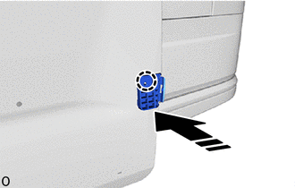
Install in this Direction |
Attach the claw and install the No. 3 side mudguard bracket LH.
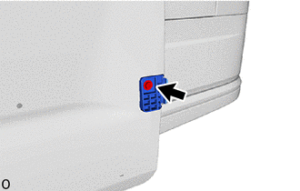
Install the screw.
75742E
9.INSTALL REAR DOOR OUTSIDE MOULDING LH
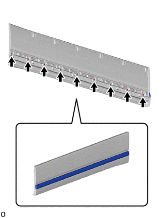
Install the rear door outside moulding LH with the 9 screws.
76966B
10.INSTALL SLIDE DOOR LOWER MUDGUARD PROTECTOR
- HINT:
-
When installing the slide door lower mudguard protector, heat the slide door mudguard sub-assembly LH using a heat light.
- Standard Value:
Part Temperature Slide Door Mudguard Sub-assembly LH 20 to 30°C (68 to 86°F)
- CAUTION:
-
2.365,2 2.698,2 false 0.5,2.333 0.5,2.667 true 0.427,2.708 0.74,2.865 0.313,0.156 10 false *a 2.76,1.927 3.073,2.083 0.313,0.156 10 false *b
*a Heated Part *b Heat Light
- ·
Do not touch the heat light and heated parts.
·Touching the heat light may result in burns.
·Touching heated parts for a long time may result in burns.
When reusing the slide door mudguard sub-assembly LH:
Using a heat light, heat the slide door mudguard sub-assembly LH.
Remove any remaining double-sided tape from the slide door mudguard sub-assembly LH.
Wipe off any tape adhesive residue with cleaner.
- NOTICE:
- ·
Installing the slide door lower mudguard protector with some double-sided tape remaining may cause poor adhesion. Perform this procedure until the tape is sufficiently removed.
·Make sure to use a cloth when removing. Using a screwdriver, etc., may cause damage and poor adhesion.
·Also, clean a new slide door mudguard sub-assembly LH.
Apply primer to the slide door mudguard sub-assembly LH on the installation area of the slide door lower mudguard protector using a brush or felt.
| *a | Scribed Line | - | - |
|
|
Primer Application | - | - |
- NOTICE:
- ·
Replace the brush or felt if it is dirty or has become hardened.
·Keep any painted surface free from primer.
·If the primer contacts a painted surface, it may leave light primer marks. Therefore, use protective tape when using liquid primer.
·Do not touch surfaces to which primer has been applied until the slide door lower mudguard protector has been attached.
Let the primer dry sufficiently.
- NOTICE:
-
Do not touch applied surfaces until the primer is dry.
- Recommended drying time:
10 minutes or more (at 23°C (73°F))
Remove the release paper of a new slide door lower mudguard protector trying not to touch the adhesional surface.
- HINT:
-
After removing the release paper, keep the exposed adhesive free from foreign matter.
Install the slide door lower mudguard protector as shown in the illustration.
- HINT:
-
Press the slide door lower mudguard protector firmly to install it.
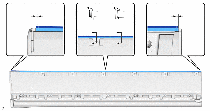
| *a | Scribed Line | - | - |
- Standard Value:
Area Dimensions C 0 to 2.0 mm (0 to 0.0787 in.)
75622C
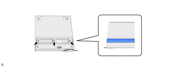
11.INSTALL NO. 2 SIDE PANEL MOULDING LH
Install the No. 2 side panel moulding LH with the 3 screws.
76922D
12.INSTALL NO. 2 SIDE MUDGUARD PROTECTOR
- HINT:
-
When installing the No. 2 side mudguard protector, heat the side mudguard sub-assembly LH using a heat light.
- Standard Value:
Part Temperature Side Mudguard Sub-assembly LH 20 to 30°C (68 to 86°F)
- CAUTION:
-
2.365,2 2.698,2 false 0.5,2.333 0.5,2.667 true 0.427,2.708 0.74,2.865 0.313,0.156 10 false *a 2.76,1.927 3.073,2.083 0.313,0.156 10 false *b
*a Heated Part *b Heat Light
- ·
Do not touch the heat light and heated parts.
·Touching the heat light may result in burns.
·Touching heated parts for a long time may result in burns.
When reusing the side mudguard sub-assembly LH:
Using a heat light, heat the side mudguard sub-assembly LH surface.
Remove any remaining double-sided tape from the side mudguard sub-assembly LH.
Wipe off any tape adhesive residue with cleaner.
- NOTICE:
- ·
Installing the No. 2 side mudguard protector with some double-sided tape remaining may cause poor adhesion. Perform this procedure until the tape is sufficiently removed.
·Make sure to use a cloth when removing. Using a screwdriver, etc., may cause damage and poor adhesion.
·Also, clean a new side mudguard sub-assembly LH.
| *a | Scribed Line |
|
|
Primer Application |
Apply primer to the side mudguard sub-assembly LH on the installation area of the No. 2 side mudguard protector using a brush or felt.
- NOTICE:
- ·
Replace the brush or felt if it is dirty or has become hardened.
·Keep any painted surface free from primer.
·If the primer contacts a painted surface, it may leave light primer marks. Therefore, use protective tape when using liquid primer.
·Do not touch surfaces to which primer has been applied until the No. 2 side mudguard protector has been attached.
Let the primer dry sufficiently.
- NOTICE:
-
Do not touch applied surfaces until the primer is dry.
- Recommended drying time:
10 minutes or more (at 23°C (73°F))
Remove the release paper of a new No. 2 side mudguard protector trying not to touch the adhesional surface.
- HINT:
-
After removing the release paper, keep the exposed adhesive free from foreign matter.
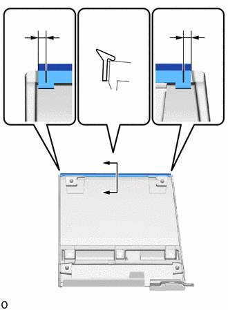
| *a | Scribed Line |
Install the No. 2 side mudguard protector as shown in the illustration.
- Standard Value:
Area Dimensions B 0 to 2.0 mm (0 to 0.0787 in.)
- HINT:
-
Press the No. 2 side mudguard protector firmly to install it.
75732B
13.INSTALL FRONT DOOR OUTSIDE MOULDING LH
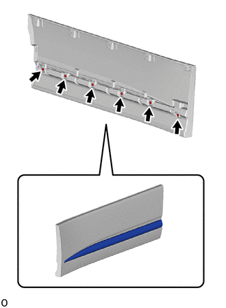
Install the front door outside moulding LH with the 6 screws.
76965A
14.INSTALL FRONT DOOR LOWER MUDGUARD PROTECTOR
- HINT:
-
When removing the front door lower mudguard protector, if the double-sided tape is difficult to remove, heat the adhesive of the front door mudguard sub-assembly LH using a heat light.
- Standard Value:
Part Temperature Front Door Mudguard Sub-assembly LH 20 to 30°C (68 to 86°F)
- CAUTION:
-
2.365,2 2.698,2 false 0.5,2.333 0.5,2.667 true 0.427,2.708 0.74,2.865 0.313,0.156 10 false *a 2.76,1.927 3.073,2.083 0.313,0.156 10 false *b
*a Heated Part *b Heat Light
- ·
Do not touch the heat light and heated parts.
·Touching the heat light may result in burns.
·Touching heated parts for a long time may result in burns.
When reusing the front door mudguard sub-assembly LH:
Using a heat light, heat the front door mudguard sub-assembly LH surface.
Remove any remaining double-sided tape from the front door mudguard sub-assembly LH.
Wipe off any tape adhesive residue with cleaner.
- NOTICE:
- ·
Installing the front door lower mudguard protector with some double-sided tape remaining may cause poor adhesion. Perform this procedure until the tape is sufficiently removed.
·Make sure to use a cloth when removing. Using a screwdriver, etc., may cause damage and poor adhesion.
·Also, clean a new front door mudguard sub-assembly LH surface.
Apply primer to the front door mudguard sub-assembly LH on the installation area of the front door lower mudguard protector using a brush or felt.
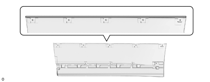
| *a | Scribed Line | - | - |
|
|
Primer Application | - | - |
- NOTICE:
- ·
Replace the brush or felt if it is dirty or has become hardened.
·Keep any painted surface free from primer.
·If the primer contacts a painted surface, it may leave light primer marks. Therefore, use protective tape when using liquid primer.
·Do not touch surfaces to which primer has been applied until the front door lower mudguard protector has been attached.
Let the primer dry sufficiently.
- NOTICE:
-
Do not touch applied surfaces until the primer is dry.
- Recommended drying time:
10 minutes or more (at 23°C (73°F))
Remove the release paper of a new front door lower mudguard protector trying not to touch the adhesional surface.
- HINT:
-
After removing the release paper, keep the exposed adhesive free from foreign matter.
Install the front door lower mudguard protector as shown in the illustration.
- HINT:
-
Press the front door lower mudguard protector firmly to install it.
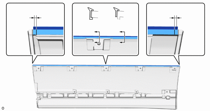
| *a | Scribed Line | - | - |
- Standard Value:
Area Dimensions C 0 to 2.0 mm (0 to 0.0787 in.)
76932A
15.INSTALL NO. 1 SIDE MUDGUARD BRACKET LH
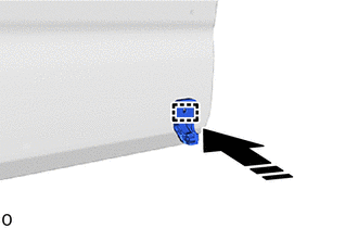
|
|
Install in this Direction |
Attach the guide and install the No. 1 side mudguard bracket LH.
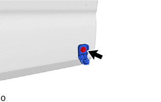
Install the screw.
76921B
16.INSTALL NO. 1 SIDE MUDGUARD PROTECTOR
- HINT:
-
When installing the No. 1 side mudguard protector, heat the fender panel mudguard sub-assembly LH using a heat light.
- Standard Value:
Part Temperature Fender Panel Mudguard Sub-assembly LH 20 to 30°C (68 to 86°F)
- CAUTION:
-
2.365,2 2.698,2 false 0.5,2.333 0.5,2.667 true 0.427,2.708 0.74,2.865 0.313,0.156 10 false *a 2.76,1.927 3.073,2.083 0.313,0.156 10 false *b
*a Heated Part *b Heat Light
- ·
Do not touch the heat light and heated parts.
·Touching the heat light may result in burns.
·Touching heated parts for a long time may result in burns.
When reusing the fender panel mudguard sub-assembly LH:
Using a heat light, heat the fender panel mudguard sub-assembly LH surface.
Remove any remaining double-sided tape from the fender panel mudguard sub-assembly LH.
Wipe off any tape adhesive residue with cleaner.
- NOTICE:
- ·
Installing the No. 1 side mudguard protector with some double-sided tape remaining may cause poor adhesion. Perform this procedure until the tape is sufficiently removed.
·Make sure to use a cloth when removing. Using a screwdriver, etc., may cause damage and poor adhesion.
·Also, clean a new fender panel mudguard sub-assembly LH surface.
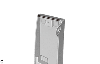
| *a | Scribed Line |
|
|
Primer Application |
Apply primer to the fender panel mudguard sub-assembly LH on the installation area of the No. 1 side mudguard protector using a brush or felt.
- NOTICE:
- ·
Replace the brush or felt if it is dirty or has become hardened.
·Keep any painted surface free from primer.
·If the primer contacts a painted surface, it may leave light primer marks. Therefore, use protective tape when using liquid primer.
·Do not touch surfaces to which primer has been applied until the No. 1 side mudguard protector has been attached.
Let the primer dry sufficiently.
- NOTICE:
-
Do not touch applied surfaces until the primer is dry.
- Recommended drying time:
10 minutes or more (at 23°C (73°F))
Remove the release paper of a new No. 1 side mudguard protector trying not to touch the adhesional surface.
- HINT:
-
After removing the release paper, keep the exposed adhesive free from foreign matter.
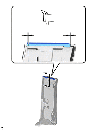
| *a | Scribed Line |
Install the No. 1 side mudguard protector as shown in the illustration.
- Standard Value:
Area Dimensions B 0 to 2.0 mm (0 to 0.0787 in.)
- HINT:
-
Press the No. 1 side mudguard protector firmly to install it.
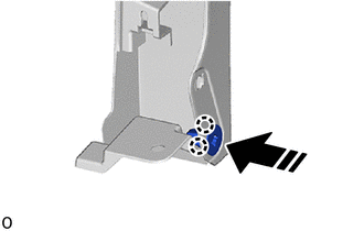
17.INSTALL GROMMET SCREW
|
|
Install in this Direction |
Attach the claw and install the grommet screw.