MIRROR (EXT) OUTER REAR VIEW MIRROR REASSEMBLY
CAUTION / NOTICE / HINT
- HINT:
- ·
Use the same procedure for the RH and LH sides.
·The procedure listed below is for the LH side.
PROCEDURE

 87966
1.INSTALL OUTER MIRROR RETRACTOR LH (w/o Panoramic View Monitor System, w/ Power Retract Mirror)
87966
1.INSTALL OUTER MIRROR RETRACTOR LH (w/o Panoramic View Monitor System, w/ Power Retract Mirror)
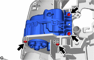
Attach the guide.
Install a new frame sub-assembly to the body with the 4 screws.
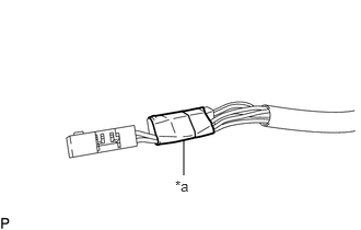
| *a | Vinyl Tape |
Wind vinyl tape around the wire harness sub-assembly to secure it.
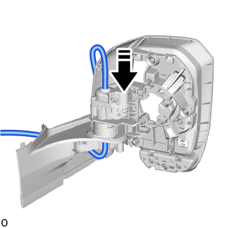

|
Install in this Direction |
Pass a new wire harness sub-assembly through the frame sub-assembly as shown in the illustration.
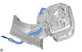
Pass the wire harness sub-assembly through the base sub-assembly.
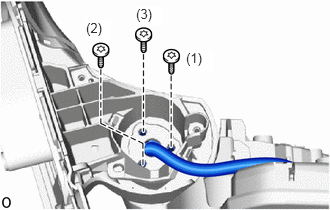
Using a T25 "TORX" socket wrench, install the base sub-assembly with 3 new screws in the order shown in the illustration.
- NOTICE:
-
When installing the base sub-assembly, check that the wire harness sub-assembly is not caught between the base sub-assembly and body. Failure to do so may cause a short circuit.
Install the actuator sub-assembly.
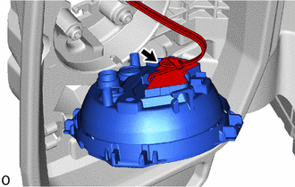
Connect the wire harness connector.
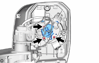
Install the actuator sub-assembly with the 3 screws.
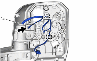
| *a | Marking |
Connect the connector and attach the guide.
Adjust the wire harness sub-assembly so that the marking is at the position shown in the illustration.
Install a new lower cover base.
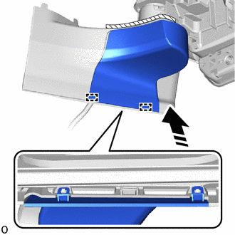
|
|
Install in this Direction |
Attach the guide as shown in the illustration.
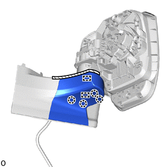
Attach the guide and claw to install the lower cover base.
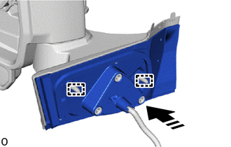
|
|
Install in this Direction |
Pass the wire harness sub-assembly through a new gasket sub-assembly and attach the guide to install a new gasket sub-assembly.
- NOTICE:
-
Make sure to replace the gasket sub-assembly with a new one.
| *a | Vinyl Tape |
Remove the vinyl tape.
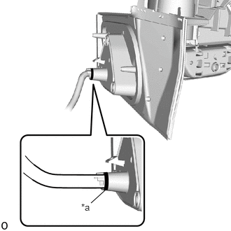
| *a | Marking |
Adjust the wire harness sub-assembly so that the marking is at the position shown in the illustration.
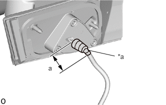
| *a | Vinyl Tape |
Wind vinyl tape around the wire harness sub-assembly to secure it.
- NOTICE:
-
Apply vinyl tape smoothly without causing wrinkles.
| Area | Measurement |
|---|---|
| a | 50 mm (1.97 in.) |
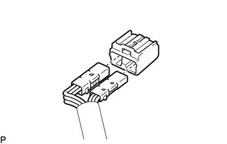
Connect each connector to a new adapter.
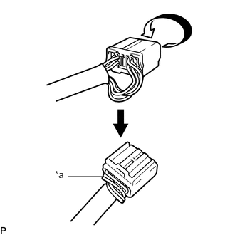
| *a | Wire Harness Routing |
Route the longer part of the wire harness sub-assembly as shown in the illustration.
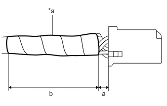
| *a | Vinyl Tape |
Wind vinyl tape around the wire harness sub-assembly to secure it.
| Area | Measurement |
|---|---|
| a | 0 to 5.0 mm (0 to 0.197 in.) |
| b | 50 mm (1.97 in.) |
81740
2.INSTALL SIDE TURN SIGNAL LIGHT ASSEMBLY LH (w/ Side Turn Signal Light)
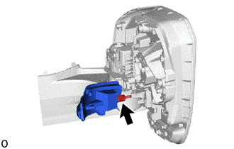
Connect the connector.
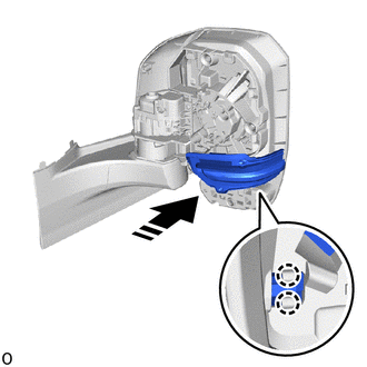
|
|
Install in this Direction |
Attach the claw to install the side turn signal light assembly LH.
Install the cover body.
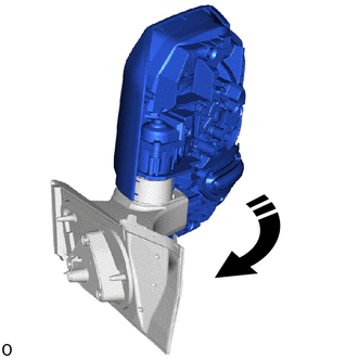
|
|
Move in this Direction |
Move the outer rear view mirror assembly LH to the forward position.
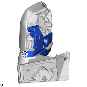
|
|
Install in this Direction |
Attach the claw to install the cover body.
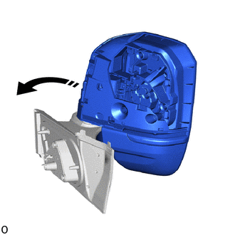
|
|
Move in this Direction |
Move the outer rear view mirror assembly LH to the driving position.
w/ Panoramic View Monitor System:
Install the side television camera assembly LH.
w/o Panoramic View Monitor System:
Attach the guide and claw.
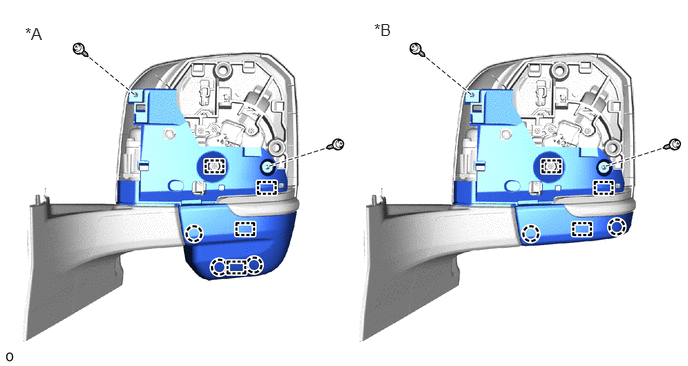
| *A | w/ Sub Mirror | *B | w/o Sub Mirror |
Install the cover body with the 2 screws.
w/ Panoramic View Monitor System:
Connect the connector and attach the wire harness clamp.
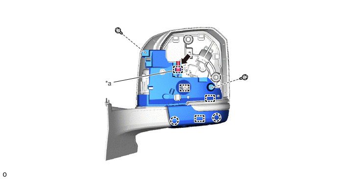
| *a | Wire Harness Clamp | - | - |
Attach the guide and claw.
Install the cover body with the 2 screws.
87945
3.INSTALL OUTER MIRROR COVER LH
87961
4.INSTALL OUTER MIRROR LH