CRUISE CONTROL DYNAMIC RADAR CRUISE CONTROL SYSTEM TERMINALS OF ECU
CHECK ECM (for 1GD-FTV)
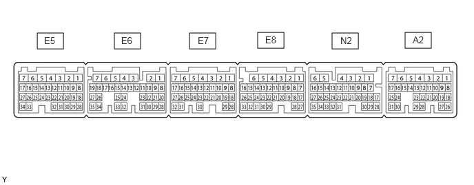
- HINT:
-
As a waterproof connector is used for the ECM, voltage, resistance and waveform inspections cannot be performed. The voltage, resistance and waveform values are provided for reference only.
| Terminal No. (Symbol) | Wiring Color | Terminal Description | Condition | Specified Condition |
|---|---|---|---|---|
| A2-13 (STP) - A2-5 (E1) | V - W-B | Stop light switch signal | Brake pedal depressed | 7.5 to 14 V |
| Brake pedal released | 0 to 1.5 V | |||
| A2-12 (ST1-) - A2-5 (E1) | B - W-B | Stop light switch signal | Engine switch on (IG), brake pedal depressed | 0 to 1.5 V |
| Engine switch on (IG), brake pedal released | 7.5 to 14 V | |||
| A2-26 (CCS) - A2-5 (E1) | B - W-B | Steering pad switch circuit | Cruise control switch not pushed | 1 MΩ or higher |
| Cruise control main switch pushed | Below 2.5 Ω | |||
| CANCEL switch pushed | 228 to 252 Ω | |||
| +RES switch pushed | 599 to 661 Ω | |||
| -SET switch pushed | 1463 to 1617 Ω |
CHECK ECM (for 7GR-FKS)
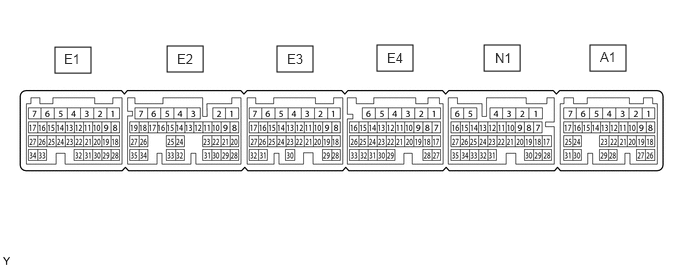
- HINT:
-
As a waterproof connector is used for the ECM, voltage, resistance and waveform inspections cannot be performed. The voltage, resistance and waveform values are provided for reference only.
| Terminal No. (Symbol) | Wiring Color | Terminal Description | Condition | Specified Condition |
|---|---|---|---|---|
| A1-13 (STP) - E3-1 (E1) | W - W-B | Stop light switch signal | Brake pedal depressed | 7.5 to 14 V |
| Brake pedal released | 0 to 1.5 V | |||
| A1-12 (ST1-) - E3-1 (E1) | B - W-B | Stop light switch signal | Engine switch on (IG), brake pedal depressed | 0 to 1.5 V |
| Engine switch on (IG), brake pedal released | 7.5 to 14 V | |||
| A1-17 (CCS) - E3-1 (E1) | B - W-B | Steering pad switch circuit | Cruise control switch not pushed | 1 MΩ or higher |
| Cruise control main switch pushed | Below 2.5 Ω | |||
| CANCEL switch pushed | 228 to 252 Ω | |||
| +RES switch pushed | 599 to 661 Ω | |||
| -SET switch pushed | 1463 to 1617 Ω |
CHECK FORWARD RECOGNITION CAMERA
- NOTICE:
- ·
Turning the engine switch on (IG) with connectors disconnected may cause DTCs to be stored. Make sure to clear the DTCs after inspection has been performed.
·Do not apply excessive force to the forward recognition camera connector.

Measure the voltage and resistance according to the value(s) in the table below.
| Terminal No. (Symbol) | Wiring Color | Terminal Description | Condition | Specified Condition |
|---|---|---|---|---|
| a9-3 (LKSW) - a9-10 (GND) | V - W-B | Steering pad switch assembly signal (distance control signal) | Engine switch on (IG), steering pad switch assembly (vehicle-to-vehicle distance control switch) on | Below 1 V |
| Engine switch on (IG), steering pad switch assembly (vehicle-to-vehicle distance control switch) off | 4.75 to 5.25 V | |||
| a9-10 (GND) - Body ground | W-B - Body ground | Ground | Always | Below 1 Ω |
| a9-7 (IGB) - a9-10 (GND) | B - W-B | Power source | Engine switch on (IG) | 11 to 14 V |
| Engine switch off | Below 1 V |