DOOR / HATCH BACK DOOR(for Wagon) ADJUSTMENT
CAUTION / NOTICE / HINT
- HINT:
-
 0.621,1.754 0.818,1.944 0.197,0.19 10 *1 2.535,1.754 2.732,1.944 0.197,0.19 10 *2
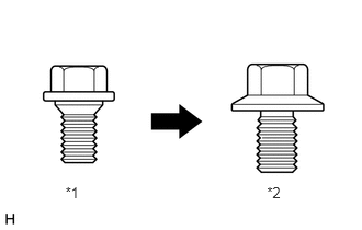
*1 Centering Bolt *2 Standard Bolt
-
Centering bolts are used to mount the door hinge to the vehicle body and door. The door cannot be adjusted with the centering bolts on. Substitute the centering bolts for standard bolts when making adjustments.
PROCEDURE

 67005
1.INSPECT BACK DOOR PANEL SUB-ASSEMBLY
67005
1.INSPECT BACK DOOR PANEL SUB-ASSEMBLY
Check that the clearance measurements of areas A to L are within the standard ranges.
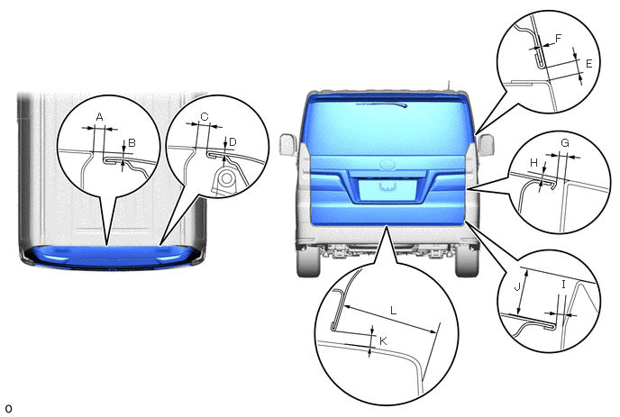
- Standard Clearance:
Area Measurement Area Measurement A 7.7 to 10.7 mm (0.303 to 0.421 in.) B 2.1 to 5.1 mm (0.0827 to 0.2008 in.) C 7.7 to 10.7 mm (0.303 to 0.421 in.) D 1.6 to 4.6 mm (0.0630 to 0.1811 in.) E 4.0 to 7.0 mm (0.157 to 0.276 in.) F -1.5 to 1.5 mm (-0.0591 to 0.0591 in.) G 3.15 to 7.15 mm (0.124 to 0.281 in.) H 2.5 mm (0.0984 in.) I 3.15 to 7.15 mm (0.124 to 0.281 in.) J 36.6 mm (1.44 in.) K 5.85 to 9.85 mm (0.230 to 0.388 in.) L 49.9 mm (1.96 in.)
67935
2.REMOVE BACK DOOR SCUFF PLATE
67005
3.ADJUST BACK DOOR PANEL SUB-ASSEMBLY
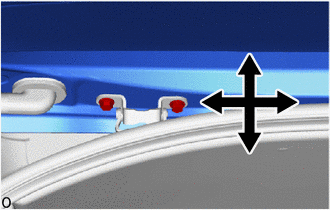
Before adjusting the upper end of the back door up and down or left and right, loosen the bolts.
Tighten the hinge bolts on the body after the adjustment.
- Torque:
- 19 N*m (194 kgf*cm, 14 ft.*lbf)
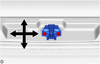
Adjust the striker position by slightly loosening the striker mounting bolts and hitting the striker with a brass bar and a hammer.
Tighten the striker mounting bolts after the adjustment.
- Torque:
- 19 N*m (194 kgf*cm, 14 ft.*lbf)
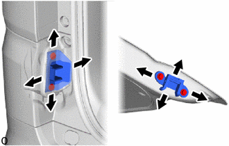
w/ Bracket:
After completing fitting adjustment, confirm the position of the back door side female stopper sub-assembly and back door side male stopper sub-assembly.
- Torque:
- 13 N*m (133 kgf*cm, 10 ft.*lbf)
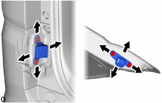
w/o Bracket:
After completing fitting adjustment, confirm the position of the back door No. 1 stopper and back door stopper cushion.
- Torque:
- 13 N*m (133 kgf*cm, 10 ft.*lbf)