EXTERIOR PANELS / TRIM FRONT BUMPER(for Wagon) REASSEMBLY
CAUTION / NOTICE / HINT
- HINT:
-
A bolt without a torque specification is shown in the standard bolt chart.
PROCEDURE

 52116A
1.INSTALL FRONT BUMPER SIDE SUPPORT LH
52116A
1.INSTALL FRONT BUMPER SIDE SUPPORT LH

|
Install in this Direction |

|
Bolt |

|
Screw |
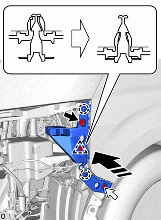
Attach the claw and clip and install the front bumper side support LH as shown in the illustration.
Install the bolt.
Install the screw.
52115A
2.INSTALL FRONT BUMPER SIDE SUPPORT RH
- HINT:
-
Use the same procedure described for the LH side.
53852B
3.INSTALL FRONT WHEEL OPENING EXTENSION PAD LH
|
|
Install in this Direction |
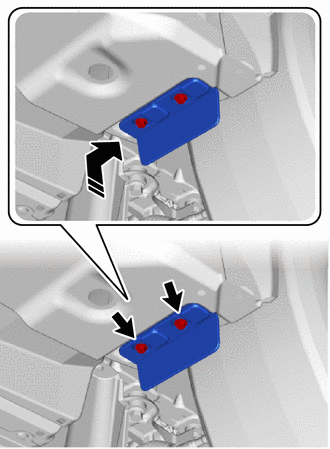
Install the front wheel opening extension pad LH as shown in the illustration.
Install the 2 screws.
53851D
4.INSTALL FRONT WHEEL OPENING EXTENSION PAD RH
- HINT:
-
Use the same procedure described for the LH side.
52021
5.INSTALL FRONT BUMPER REINFORCEMENT SUB-ASSEMBLY
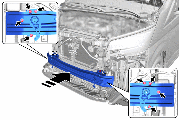
Attach the hook and install the front bumper reinforcement sub-assembly as shown in the illustration.
Install the 8 bolts.
- Torque:
- 65 N*m (663 kgf*cm, 48 ft.*lbf)
|
|
Install in this Direction | - | - |
52611
6.INSTALL FRONT BUMPER ENERGY ABSORBER
|
|
Install in this Direction |
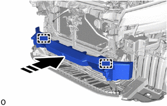
Attach the guide and install the front bumper energy absorber as shown in the illustration.
53286F
7.INSTALL RADIATOR SIDE AIR SEAL LH
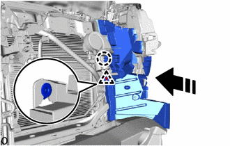
|
|
Install in this Direction |
Attach the clip and claw and install the radiator side air seal LH as shown in the illustration.
53285N
8.INSTALL RADIATOR SIDE AIR SEAL RH
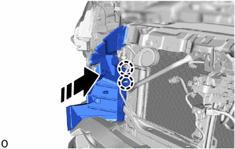
|
|
Install in this Direction |
Attach the claw and install the radiator side air seal RH as shown in the illustration.
17311B
9.INSTALL NO. 1 AIR INLET DUCT (for 1GD-FTV)
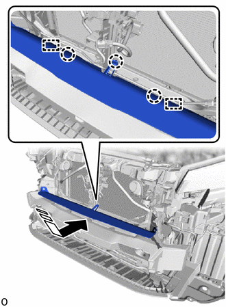
|
|
Install in this Direction |
Attach the guide and claw and install the No. 1 air inlet duct as shown in the illustration.
Install the 2 clips.
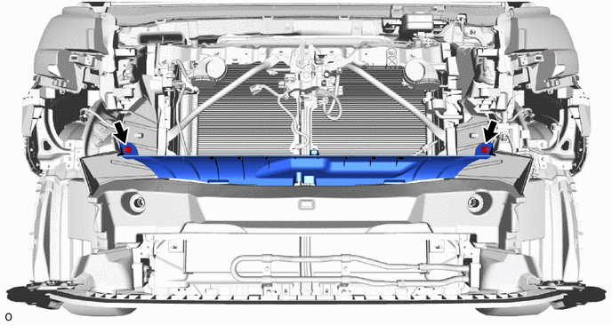
53112E
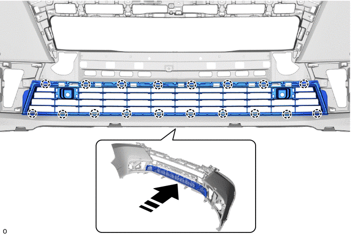
10.INSTALL LOWER NO. 1 RADIATOR GRILLE
Attach the claw and install the lower No. 1 radiator grille as shown in the illustration.
|
|
Install in this Direction | - | - |
53128H
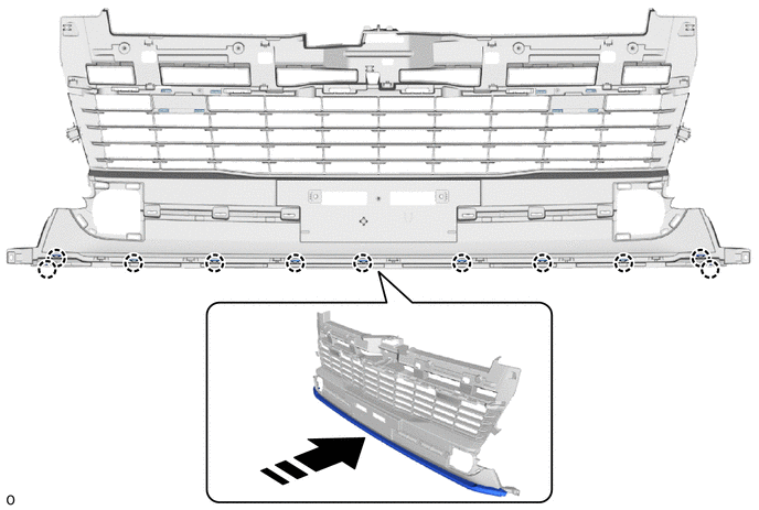
11.INSTALL NO. 8 RADIATOR GRILLE MOULDING
Attach the claw and install the No. 8 radiator grille moulding as shown in the illustration.
|
|
Install in this Direction | - | - |
53127F
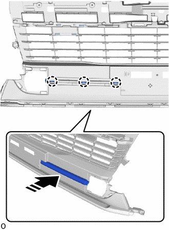
12.INSTALL NO. 7 RADIATOR GRILLE MOULDING
|
|
Install in this Direction |
Attach the claw and install the No. 7 radiator grille moulding as shown in the illustration.
53126M
13.INSTALL NO. 6 RADIATOR GRILLE MOULDING
- HINT:
-
Use the same procedure described for the LH side.
53102A
14.INSTALL LOWER RADIATOR GRILLE SUB-ASSEMBLY
Attach the claw and install the lower radiator grille sub-assembly as shown in the illustration.
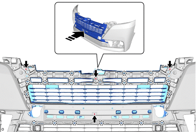
Install the 4 screws.
52713A
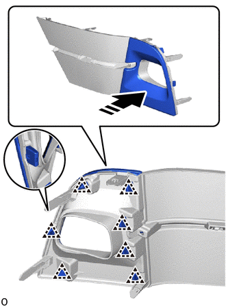
15.INSTALL FRONT BUMPER NO. 1 SIDE MOULDING LH
|
|
Install in this Direction |
Attach the clip and install the front bumper No. 1 side moulding LH as shown in the illustration.
52712
16.INSTALL FRONT BUMPER NO. 1 SIDE MOULDING RH
- HINT:
-
Use the same procedure described for the LH side.
52713D
17.INSTALL FRONT BUMPER NO. 2 SIDE MOULDING LH

|
|
Install in this Direction |
Attach the claw and install the front bumper No. 2 side moulding LH as shown in the illustration.
Install the 2 screws.
52712F
18.INSTALL FRONT BUMPER NO. 2 SIDE MOULDING RH
- HINT:
-
Use the same procedure described for the LH side.
81482C
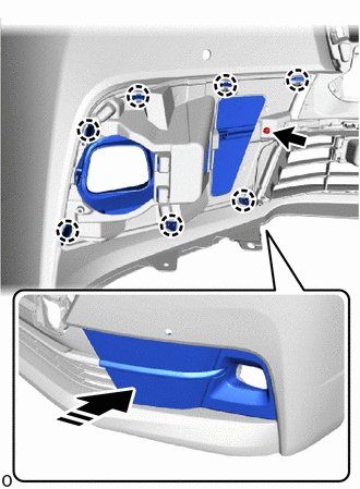
19.INSTALL FOG LIGHT COVER LH
|
|
Install in this Direction |
Attach the claw and install the fog light cover LH as shown in the illustration.
Install the screw.
81481E
20.INSTALL FOG LIGHT COVER RH
- HINT:
-
Use the same procedure described for the LH side.
81482M
21.INSTALL FOG LIGHT BRACKET LH

|
|
Install in this Direction |
Install the fog light bracket LH with the 2 screws as shown in the illustration.
81481R
22.INSTALL FOG LIGHT BRACKET RH
- HINT:
-
Use the same procedure described for the LH side.
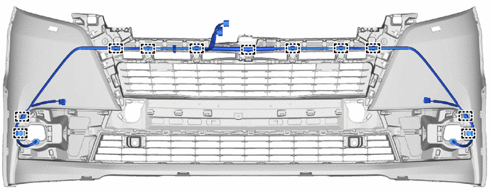
82113
23.INSTALL NO. 3 ENGINE ROOM WIRE
Attach the clamp and install the No. 3 engine room wire.
81220
24.INSTALL FOG LIGHT ASSEMBLY LH
81210A
25.INSTALL FOG LIGHT ASSEMBLY RH
- HINT:
-
Use the same procedure described for the LH side.
89347B
26.INSTALL FRONT CORNER ULTRASONIC SENSOR RETAINER (w/ TOYOTA Parking Assist-sensor System)
89341K
27.INSTALL FRONT CORNER ULTRASONIC SENSOR (w/ TOYOTA Parking Assist-sensor System)
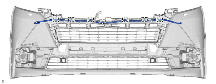
28.INSTALL HEADLIGHT CLEANER HOSE ASSEMBLY (w/ Headlight Cleaner System)
Attach the clamp and install the headlight cleaner hose assembly.
85208A
29.INSTALL HEADLIGHT WASHER ACTUATOR SUB-ASSEMBLY LH (w/ Headlight Cleaner System)
85207A
30.INSTALL HEADLIGHT WASHER ACTUATOR SUB-ASSEMBLY RH (w/ Headlight Cleaner System)
- HINT:
-
Use the same procedure described for the LH side.
85354
31.INSTALL HEADLIGHT WASHER COVER LH (w/ Headlight Cleaner System)
85353
32.INSTALL HEADLIGHT WASHER COVER RH (w/ Headlight Cleaner System)
- HINT:
-
Use the same procedure described for the LH side.