EXTERIOR PANELS / TRIM FRONT BUMPER(for Wagon) DISASSEMBLY
PROCEDURE

 85354
1.REMOVE HEADLIGHT WASHER COVER LH (w/ Headlight Cleaner System)
85354
1.REMOVE HEADLIGHT WASHER COVER LH (w/ Headlight Cleaner System)
85353
2.REMOVE HEADLIGHT WASHER COVER RH (w/ Headlight Cleaner System)
- HINT:
-
Use the same procedure described for the LH side.
85208A
3.REMOVE HEADLIGHT WASHER ACTUATOR SUB-ASSEMBLY LH (w/ Headlight Cleaner System)
85207A
4.REMOVE HEADLIGHT WASHER ACTUATOR SUB-ASSEMBLY RH (w/ Headlight Cleaner System)
- HINT:
-
Use the same procedure described for the LH side.
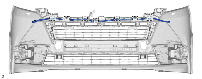
5.REMOVE HEADLIGHT CLEANER HOSE ASSEMBLY (w/ Headlight Cleaner System)
Detach the clamp and remove the headlight cleaner hose assembly.
89341K
6.REMOVE FRONT CORNER ULTRASONIC SENSOR (w/ TOYOTA Parking Assist-sensor System)
89347B
7.REMOVE FRONT CORNER ULTRASONIC SENSOR RETAINER (w/ TOYOTA Parking Assist-sensor System)
81220
8.REMOVE FOG LIGHT ASSEMBLY LH
81210A
9.REMOVE FOG LIGHT ASSEMBLY RH
- HINT:
-
Use the same procedure described for the LH side.
81482M
10.REMOVE FOG LIGHT BRACKET LH
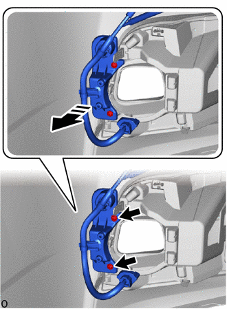

|
Remove in this Direction |
Remove the 2 screws.
Remove the fog light bracket LH as shown in the illustration.
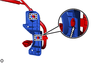

|
Protective Tape |
Using a screwdriver, detach the wire harness clamp.
- HINT:
-
Tape the screwdriver tip before use.
81481R
11.REMOVE FOG LIGHT BRACKET RH
- HINT:
-
Use the same procedure described for the LH side.
81482C
12.REMOVE FOG LIGHT COVER LH
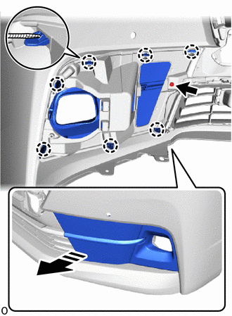
|
|
Remove in this Direction |
|
|
Protective Tape |
Remove the screw.
Using a screwdriver, detach the claw and remove the fog light cover LH as shown in the illustration.
- HINT:
-
Tape the screwdriver tip before use.
81481E
13.REMOVE FOG LIGHT COVER RH
- HINT:
-
Use the same procedure described for the LH side.
52713D
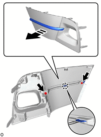
14.REMOVE FRONT BUMPER NO. 2 SIDE MOULDING LH
|
|
Remove in this Direction |
|
|
Protective Tape |
Remove the 2 screws.
Using a screwdriver, detach the claw and remove the front bumper No. 2 side moulding LH as shown in the illustration.
- HINT:
-
Tape the screwdriver tip before use.
52712F
15.REMOVE FRONT BUMPER NO. 2 SIDE MOULDING RH
- HINT:
-
Use the same procedure described for the LH side.
52713A
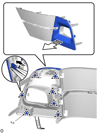
16.REMOVE FRONT BUMPER NO. 1 SIDE MOULDING LH
| *a | Clip A |
|
|
Remove in this Direction (1) |

|
Remove in this Direction (2) |
Using needle-nose pliers, detach clip A to create a gap and insert moulding remover A into the gap.
Then, while widening the gap, detach the other clip in the order shown in the illustration and remove the front bumper No. 1 side moulding LH.
52712
17.REMOVE FRONT BUMPER NO. 1 SIDE MOULDING RH
- HINT:
-
Use the same procedure described for the LH side.
53102A
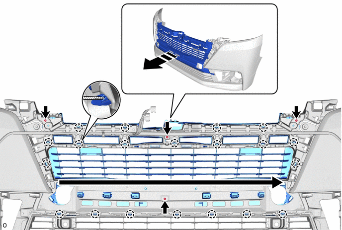
18.REMOVE LOWER RADIATOR GRILLE SUB-ASSEMBLY
Remove the 4 screws.
Using a screwdriver, detach the claw and remove the lower radiator grille sub-assembly as shown in the illustration.
- HINT:
-
Tape the screwdriver tip before use.
|
|
Remove in this Direction | 
|
Order of Removal |
|
|
Protective Tape | - | - |
53127F
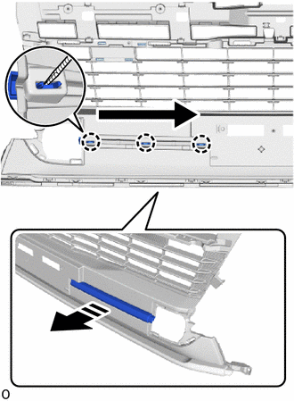
19.REMOVE NO. 7 RADIATOR GRILLE MOULDING
|
|
Remove in this Direction |
|
|
Order of Removal |
|
|
Protective Tape |
Using a screwdriver, detach the claw and remove the No. 7 radiator grille moulding as shown in the illustration.
- HINT:
-
Tape the screwdriver tip before use.
53126M
20.REMOVE NO. 6 RADIATOR GRILLE MOULDING
- HINT:
-
Use the same procedure described for the LH side.
53128H
21.REMOVE NO. 8 RADIATOR GRILLE MOULDING
Using a screwdriver, detach the claw and remove the No. 8 radiator grille moulding as shown in the illustration.
- HINT:
-
Tape the screwdriver tip before use.
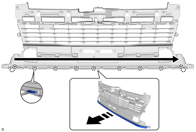
|
|
Remove in this Direction |
|
Order of Removal |
|
|
Protective Tape | - | - |
82113
22.REMOVE NO. 3 ENGINE ROOM WIRE
Detach the clamp and remove the No. 3 engine room wire.
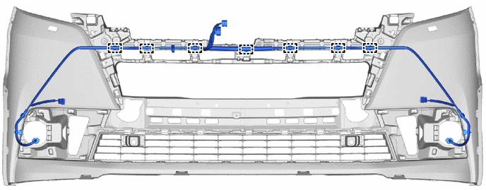
53112E
23.REMOVE LOWER NO. 1 RADIATOR GRILLE
Using a screwdriver, detach the claw and remove the lower No. 1 radiator grille as shown in the illustration.
- HINT:
-
Tape the screwdriver tip before use.
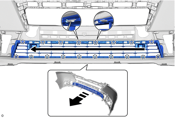
|
|
Remove in this Direction |
|
Order of Removal |
|
|
Protective Tape | - | - |
17311B
24.REMOVE NO. 1 AIR INLET DUCT (for 1GD-FTV)
Remove the 2 clips.
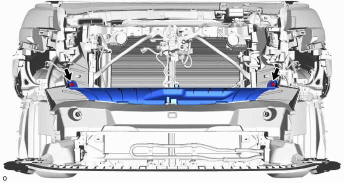
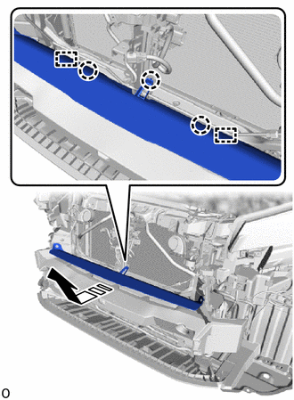
|
|
Remove in this Direction |
Detach the claw and guide and remove the No. 1 air inlet duct as shown in the illustration.
53286F
25.REMOVE RADIATOR SIDE AIR SEAL LH
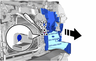
|
|
Remove in this Direction |
|
|
Protective Tape |
Using a clip remover, detach the clip and claw and remove the radiator side air seal LH as shown in the illustration.
- HINT:
-
Tape the clip remover tip before use.
53285N
26.REMOVE RADIATOR SIDE AIR SEAL RH
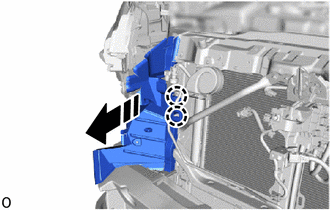
|
|
Remove in this Direction |
Detach the claw and remove the radiator side air seal RH as shown in the illustration.
52611
27.REMOVE FRONT BUMPER ENERGY ABSORBER
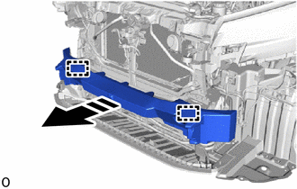
|
|
Remove in this Direction |
Detach the guide and remove the front bumper energy absorber as shown in the illustration.
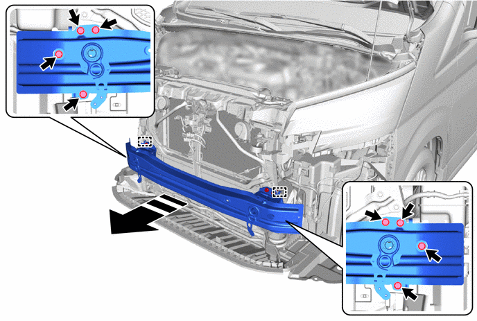
52021
28.REMOVE FRONT BUMPER REINFORCEMENT SUB-ASSEMBLY
Remove the 8 bolts.
Detach the hook and remove the front bumper reinforcement sub-assembly as shown in the illustration.
|
|
Remove in this Direction | - | - |
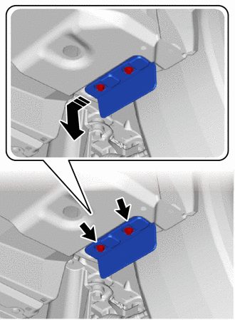
53852B
29.REMOVE FRONT WHEEL OPENING EXTENSION PAD LH
|
|
Remove in this Direction |
Remove the 2 screws.
Remove the front wheel opening extension pad LH as shown in the illustration.
53851D
30.REMOVE FRONT WHEEL OPENING EXTENSION PAD RH
- HINT:
-
Use the same procedure described for the LH side.
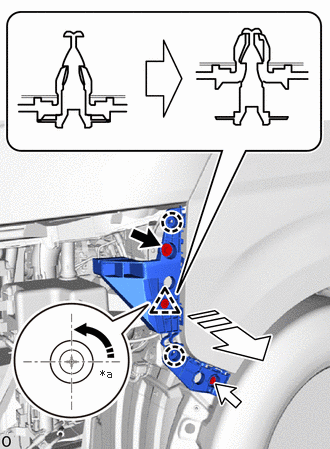
52116A
31.REMOVE FRONT BUMPER SIDE SUPPORT LH
| *a | 90° |
|
|
Rotation in this Direction |
|
|
Remove in this Direction |
|
|
Bolt |

|
Screw |
Remove the bolt.
Remove the screw.
Using a screwdriver, turn the clip 90° and detach the clip and claw and remove the front bumper side retainer LH as shown in the illustration.
52115A
32.REMOVE FRONT BUMPER SIDE SUPPORT RH
- HINT:
-
Use the same procedure described for the LH side.