RM35X0E _51 Engine / Hybrid System _078825 STOP AND START _0382334 STOP AND START SYSTEM C

STOP AND START  STOP AND START SYSTEM  P323A19  Backup Boost Converter "A" Circuit Current Above Threshold  


DESCRIPTION

A backup boost converter is built into the engine stop and start ECU.

The backup boost converter helps maintain battery voltage to prevent various functions from failing if power source voltage supplied from the backup boost converter drops due to the high electrical load when the engine is restarted by stop and start control.

The backup boost converter helps maintain the power source voltage if the battery voltage drops due to the high electrical load when the engine is restarted by stop and start control.

HINT:

A relay function and fuse function are provided in the backup boost converter.

If there is a malfunction in any of the electrical system circuits connected to the backup boost converter, the fuse and relay functions shut off the malfunctioning circuit to protect other circuits (remains shut off until next trip).

When the electrical system circuit is shut off, power to the circuit is cut off, causing any systems connected to the circuit to be disabled.

The fuse function is reset* when the ignition switch is turned off. If the malfunction still exists in the electrical system circuit that has been shut off by the relay function, it will be shut off again by the relay and fuse functions the next time the ignition switch is turned to ON.

*: A semiconductor fuse self resets according to electric signal.

The backup boost converter supplies power to:
·

Front radar sensor system

·

Electronically controlled brake system

·

Pre-collision system

·

Audio and visual system

·

Navigation system

·

Digital rear-view mirror system

·

Wireless door lock control system

·

Lighting system (INT)

·

CAN communication system

·

Meter / gauge system

·

Panoramic view monitor system

·

Dynamic radar cruise cintrol system

·

Front camera system

·

Tire pressure warning system

·

Blind spot monitor system


DTC No. Detection Item DTC Detection Condition Trouble Area Warning Indicate Memory Note
P323A19 Backup Boost Converter "A" Circuit Current Above Threshold The following condition continues for 1 second or more (1 trip detection logic):
·

Overcurrent is detected at the B41, B42, B43 and IG41 terminals in the engine stop and start ECU


·

Wire harness or connector

·

Door control receiver*1

·

Inner rear view mirror assembly*2

·

No. 1 integration relay (DOME CUT NO.2 relay)

·

Radio and display receiver assembly

·

Navigation ECU*3

·

Network gateway ECU

·

Instrument panel junction block assembly (main body ECU (multiplex network body ECU))

·

Millimeter Wave Radar Sensor Assembly*4

·

Parking Assist ECU*5*9

·

Inner rear view mirror assembly*6

·

Blind spot monitor sensor LH*7

·

Blind spot monitor sensor RH*7

·

Tire pressure warning ECU and receiver*8

·

NO. 1 interior illumination light assembly (slide door illumination)

·

NO. 2 interior illumination light assembly (slide door illumination)

·

NO. 1 interior illumination light assembly (quarter trim illumination)

·

NO. 2 interior illumination light assembly (quarter trim illumination)

·

Spot light assembly (for front LH)

·

Spot light assembly (for rear LH)

·

Spot light assembly (for front RH)

·

spot light assembly (for rear RH)

·

Engine stop and start ECU


Blinks DTC stored SAE Code: P323A

·

*1: w/ Wireless Door Lock Control System

·

*2: w/ Digital Rear-View Mirror System

·

*3: w/ Navigation System

·

*4: w/ Front Radar Sensor System

·

*5: w/ Panoramic View Monitor System

·

*6: w/ Rear View Mirror System

·

*7: w/ Blind Spot Monitor System

·

*8: w/ Tire Pressure Warning System

·

*9: Production date from 2019/06 to 2023/10


CONFIRMATION DRIVING PATTERN

CONFIRMATION AFTER TROUBLESHOOTING


HINT:
·

If the cable is disconnected from the battery terminal, stop and start control is prohibited until refresh charge is completed.

In this case, let the vehicle idle to complete the refresh charge. The refresh charge is complete when the Data List item "Status of Battery Charge Control" changes from "Refresh Charge Mode". (Usually, idling the engine for 5 to 60 minutes with the battery fluid temperature at 11°C (51°F) or higher, the refresh charge will be completed.)

·

If the GTS is not available and the Data List item "Status of Battery Charge Control" cannot be checked, charge the battery by idling the engine for approximately 5 to 60 minutes or driving the vehicle, and then drive the vehicle and check that stop and start control operates.

If the engine is started with the hood open, the system determines that a jump start has occurred. Therefore, make sure that the hood is closed before starting the engine and driving the vehicle.

·

After the refresh charge completes, turn the ignition switch off, wait for at least 30 seconds, and then start the engine again. If the vehicle enters refresh charge mode again while the engine is idling, the initial refresh charge did not properly complete, so wait for the refresh charge to complete.

·

Allow the engine to idle for 3 minutes after it is warmed up and check that the engine idle speed is within 50 rpm of the target idle speed.


a.

Connect the GTS to the DLC3.


b.

Turn the ignition switch to ON.


c.

Turn the GTS on.


d.

Clear the DTCs.

Powertrain > Stop and Start > Clear DTCs
50002 392

e.

Start the engine and warm it up.


f.

Drive the vehicle at 7 km/h (4 mph) or more.

CAUTION:

When performing Confirmation Driving Pattern, obey all speed limits and traffic laws.


g.

for Automatic Transmission:

Depress the brake pedal and stop the vehicle.

for Manual Transmission:

Stop the vehicle, move the shift lever to neutral and release the clutch pedal.


h.

Keep the engine stopped by stop and start control for 1 second or more. (for Automatic Transmission: Keep the shift lever in D.)


i.

for Automatic Transmission:

Release the brake pedal with the shift lever in D to start the engine.

for Manual Transmission:

Depress the clutch pedal and start the engine.

HINT:

If the engine cranks slowly when the engine is restarted, it can be determined that the battery voltage is low.


j.

Check that DTCs are not output.

Powertrain > Stop and Start > Trouble Codes
50001 392


STOP AND START SYSTEM OPERATION CHECK


HINT:
·

If the cable is disconnected from the battery terminal, stop and start control is prohibited until refresh charge is completed.

In this case, let the vehicle idle to complete the refresh charge. The refresh charge is complete when the Data List item "Status of Battery Charge Control" changes from "Refresh Charge Mode". (Usually, idling the engine for 5 to 60 minutes with the battery fluid temperature at 11°C (51°F) or higher, the refresh charge will be completed.)

·

If the GTS is not available and the Data List item "Status of Battery Charge Control" cannot be checked, charge the battery by idling the engine for approximately 5 to 60 minutes or driving the vehicle, and then drive the vehicle and check that stop and start control operates.

If the engine is started with the hood open, the system determines that a jump start has occurred. Therefore, make sure that the hood is closed before starting the engine and driving the vehicle.

·

After the refresh charge completes, turn the ignition switch off, wait for at least 30 seconds, and then start the engine again. If the vehicle enters refresh charge mode again while the engine is idling, the initial refresh charge did not properly complete, so wait for the refresh charge to complete.


a.

Start the engine and warm it up.


b.

Turn the air conditioning system off.


c.

Drive the vehicle at 7 km/h (4 mph) or more.

CAUTION:

When performing Confirmation Driving Pattern, obey all speed limits and traffic laws.


d.

for Automatic Transmission:

Depress the brake pedal and stop the vehicle.

for Manual Transmission:

Stop the vehicle, move the shift lever to neutral and release the clutch pedal.


e.

Allow the engine to stop by stop and start control. (for Automatic Transmission: Keep the shift lever in D.)


f.

for Automatic Transmission:

Release the brake pedal with the shift lever in D to start the engine.

for Manual Transmission:

Depress the clutch pedal and start the engine.


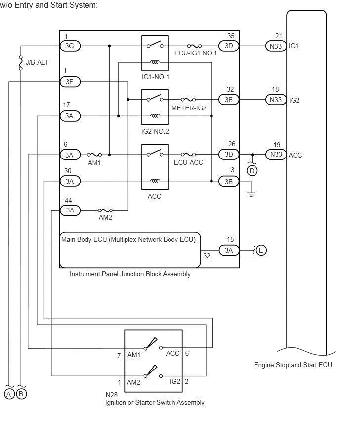
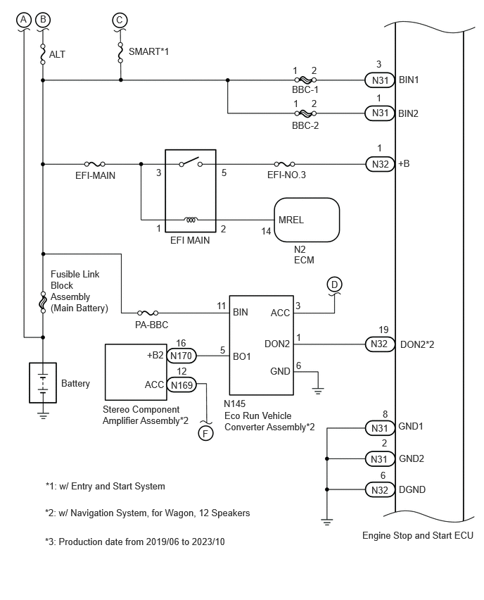
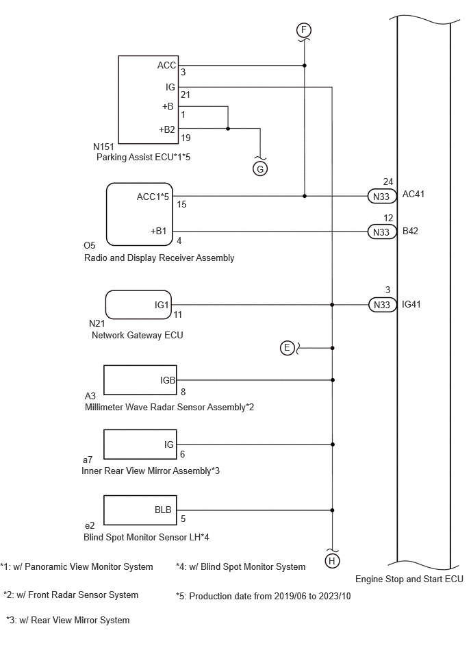
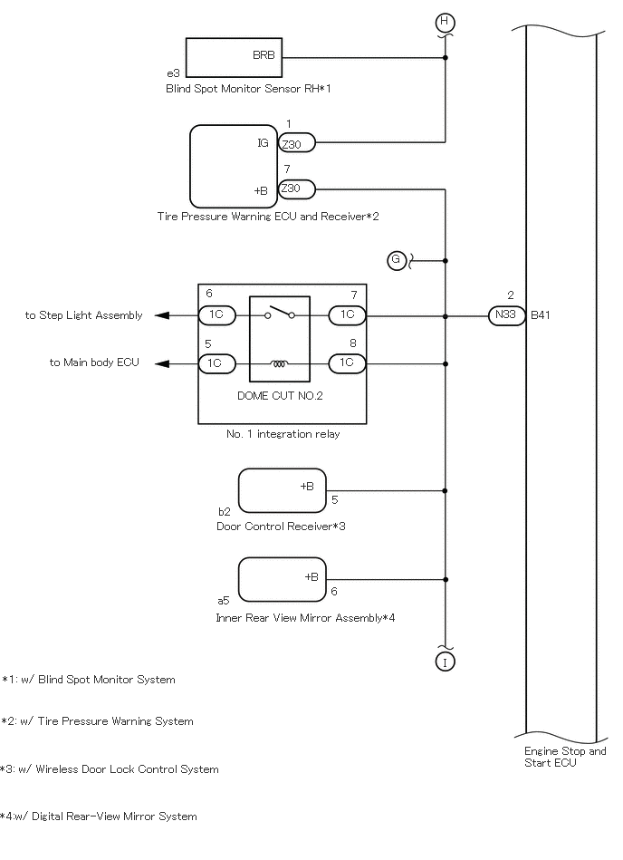
WIRING DIAGRAM
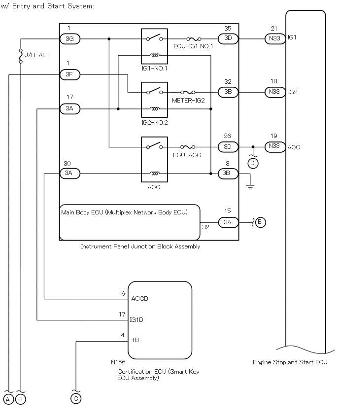
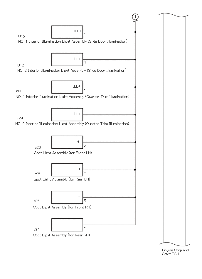
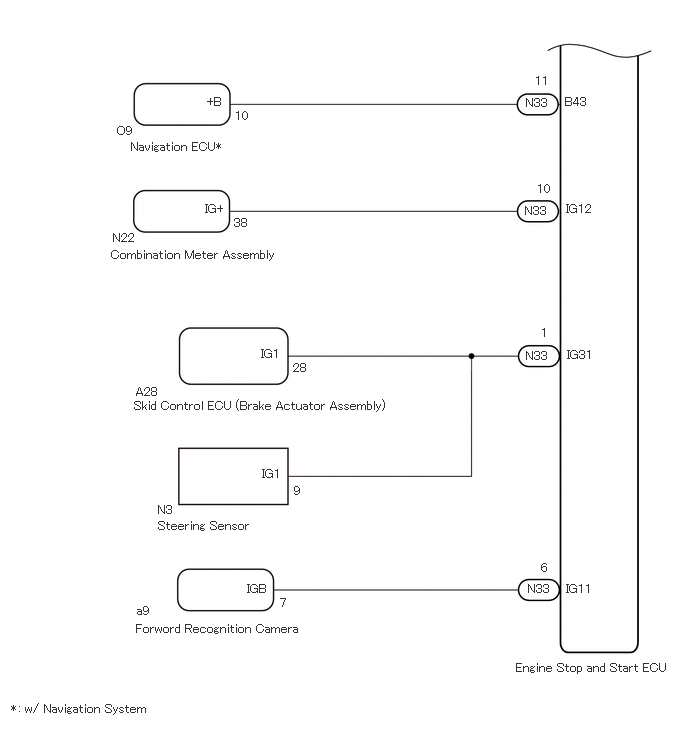
A448929E01
1.719,5.135 4.573,5.448 2.854,0.313 10 false Instrument Panel Junction Block Assembly 5.354,7.583 7.083,7.906 1.729,0.323 10 false Engine Stop and Start ECU 0.521,1.094 1.115,1.281 0.594,0.188 10 false J/B-ALT 3,2.521 3.792,2.813 0.792,0.292 10 false IG2-NO.2 3.125,3.885 3.917,4.177 0.792,0.292 10 false ACC 3.677,0.906 4.677,1.156 1,0.25 10 false ECU-IG1 NO.1 3.667,3.208 4.458,3.5 0.792,0.292 10 false ECU-ACC 3.646,2.052 4.438,2.344 0.792,0.292 10 false METER-IG2 0.125,8.375 0.469,8.594 0.344,0.219 10 false A 6.083,0.719 6.875,1.01 0.792,0.292 10 false IG1 6.094,1.875 6.885,2.167 0.792,0.292 10 false IG2 6.083,3.042 6.875,3.333 0.792,0.292 10 false ACC 5.698,0.74 6.49,1.031 0.792,0.292 10 false N33 4.74,4.625 5.531,4.917 0.792,0.292 10 false 3A 4.75,0.729 5.542,1.021 0.792,0.292 10 false 3D 4.75,1.865 5.542,2.156 0.792,0.292 10 false 3B 4.708,3.583 5.5,3.875 0.792,0.292 10 false 3B 4.74,3.031 5.531,3.323 0.792,0.292 10 false 3D 1.396,0.75 2.188,1.042 0.792,0.292 10 false 3G 1.396,1.5 2.188,1.792 0.792,0.292 10 false 3F 1.396,2.219 2.188,2.51 0.792,0.292 10 false 3A 1.375,3.583 2.167,3.875 0.792,0.292 10 false 3A 5.729,0.531 5.99,0.75 0.26,0.219 10 false 21 5.719,1.646 5.969,1.927 0.25,0.281 10 false 18 5.719,2.802 6.083,3.01 0.365,0.208 10 false 19 4.75,0.531 5.542,0.823 0.792,0.292 10 false 35 4.75,1.656 5.542,1.948 0.792,0.292 10 false 32 4.74,2.802 5.531,3.094 0.792,0.292 10 false 26 4.781,3.385 5.115,3.635 0.333,0.25 10 false 3 1.302,4.417 4.479,5.083 3.177,0.667 10 false Main Body ECU (Multiplex Network Body ECU) 1.427,0.521 2.219,0.813 0.792,0.292 10 false 1 1.406,1.26 2.198,1.552 0.792,0.292 10 false 1 1.406,1.979 2.198,2.271 0.792,0.292 10 false 17 1.354,3.385 2.146,3.677 0.792,0.292 10 false 30 4.74,4.385 5,4.594 0.26,0.208 10 false 15 4.281,4.729 4.49,4.948 0.208,0.219 10 false 32 2.354,7.583 3.458,7.896 1.104,0.313 10 false N156 2.49,7.781 4.313,8.177 1.823,0.396 10 false Certification ECU (Smart Key ECU Assembly) 2.563,7.01 2.781,7.25 0.219,0.24 10 false 4 2.51,6.573 3.615,6.885 1.104,0.313 10 false 17 2.781,7.115 3.25,7.344 0.469,0.229 10 false +B 2.781,6.24 3.885,6.552 1.104,0.313 10 false ACCD 5.688,1.865 6.031,2.177 0.344,0.313 10 false N33 5.688,3.01 6.479,3.302 0.792,0.292 10 false N33 1.563,8.354 1.865,8.583 0.302,0.229 10 false C 0.396,8.365 0.74,8.583 0.344,0.219 10 false B 2.75,6.688 3.219,6.917 0.469,0.229 10 false IG1D 3,1.375 3.792,1.667 0.792,0.292 10 false IG1-NO.1 2.5,6.135 2.813,6.333 0.313,0.198 10 false 16 0.01,0.031 4.781,0.271 4.771,0.24 12 false w/ Entry and Start System: 5.302,3.375 5.458,3.573 0.156,0.198 10 false D 5.458,4.615 5.615,4.813 0.156,0.198 10 false E

A448933E01
1.469,5.677 4.323,5.99 2.854,0.313 10 false Instrument Panel Junction Block Assembly 5.354,7.583 7.083,7.906 1.729,0.323 10 false Engine Stop and Start ECU 1.854,3.344 2.333,3.604 0.479,0.26 10 false AM1 0.542,1.229 1.135,1.417 0.594,0.188 10 false J/B-ALT 2.979,2.677 3.771,2.969 0.792,0.292 10 false IG2-NO.2 3.115,4.042 3.906,4.333 0.792,0.292 10 false ACC 2.083,4.49 2.875,4.781 0.792,0.292 10 false AM2 1.344,2.948 2.135,3.24 0.792,0.292 10 false 6 3.677,1.031 4.677,1.281 1,0.25 10 false ECU-IG1 NO.1 3.667,3.333 4.458,3.625 0.792,0.292 10 false ECU-ACC 3.615,2.188 4.406,2.479 0.792,0.292 10 false METER-IG2 0.135,8.208 0.479,8.427 0.344,0.219 10 false A 6.083,0.875 6.875,1.167 0.792,0.292 10 false IG1 6.094,2.021 6.885,2.313 0.792,0.292 10 false IG2 6.083,3.177 6.875,3.469 0.792,0.292 10 false ACC 5.688,0.885 6.479,1.177 0.792,0.292 10 false N33 4.74,5.177 5.531,5.469 0.792,0.292 10 false 3A 4.74,0.875 5.531,1.167 0.792,0.292 10 false 3D 4.74,2.01 5.531,2.302 0.792,0.292 10 false 3B 4.74,3.74 5.531,4.031 0.792,0.292 10 false 3B 4.74,3.156 5.531,3.448 0.792,0.292 10 false 3D 1.375,0.875 2.167,1.167 0.792,0.292 10 false 3G 1.385,1.635 2.177,1.927 0.792,0.292 10 false 3F 1.375,2.354 2.167,2.646 0.792,0.292 10 false 3A 1.385,3.729 2.177,4.021 0.792,0.292 10 false 3A 1.396,4.333 2.188,4.625 0.792,0.292 10 false 3A 5.802,0.667 6.063,0.885 0.26,0.219 10 false 21 5.729,1.792 5.979,2.073 0.25,0.281 10 false 18 5.76,2.958 6.125,3.167 0.365,0.208 10 false 19 4.792,0.667 5.583,0.958 0.792,0.292 10 false 35 4.781,1.792 5.573,2.083 0.792,0.292 10 false 32 4.813,2.938 5.604,3.229 0.792,0.292 10 false 26 4.865,3.49 5.198,3.74 0.333,0.25 10 false 3 1.292,4.948 4.469,5.615 3.177,0.667 10 false Main Body ECU (Multiplex Network Body ECU) 1.354,0.677 2.146,0.969 0.792,0.292 10 false 1 1.333,1.396 2.125,1.688 0.792,0.292 10 false 1 1.323,2.115 2.115,2.406 0.792,0.292 10 false 17 1.354,3.51 2.146,3.802 0.792,0.292 10 false 30 1.365,4.125 2.156,4.417 0.792,0.292 10 false 44 4.781,4.948 5.042,5.156 0.26,0.208 10 false 15 3.896,7.938 4.688,8.229 0.792,0.292 10 false 2 4.281,5.292 4.49,5.51 0.208,0.219 10 false 32 2.229,8.219 3.333,8.531 1.104,0.313 10 false N28 2.219,8.375 4.667,8.719 2.448,0.344 10 false Ignition or Starter Switch Assembly 2.479,7.958 2.698,8.198 0.219,0.24 10 false 1 3.906,7.344 4.156,7.531 0.25,0.188 10 false 6 2.469,7.396 3.573,7.708 1.104,0.313 10 false 7 2.677,7.958 3.146,8.188 0.469,0.229 10 false AM2 3.5,7.344 4.604,7.656 1.104,0.313 10 false ACC 5.688,2.01 6.031,2.323 0.344,0.313 10 false N33 5.698,3.156 6.49,3.448 0.792,0.292 10 false N33 5.26,3.51 5.563,3.74 0.302,0.229 10 false D 0.396,8.198 0.74,8.417 0.344,0.219 10 false B 2.688,7.375 3.156,7.604 0.469,0.229 10 false AM1 3.583,7.938 3.99,8.156 0.406,0.219 10 false IG2 1.375,3.177 2.167,3.469 0.792,0.292 10 false 3A 2.99,1.531 3.781,1.823 0.792,0.292 10 false IG1-NO.1 0,0 4.958,0.24 4.958,0.24 12 false w/o Entry and Start System: 5.458,5.177 5.615,5.375 0.156,0.198 10 false E

A448930E02
0.302,0.198 0.542,0.417 0.24,0.219 10 false A 0.906,5.583 1.708,5.833 0.802,0.25 10 false Battery 4.323,1.24 5.125,1.49 0.802,0.25 10 false BBC-1 4.323,1.771 5.125,2.021 0.802,0.25 10 false BBC-2 4.333,0.958 4.573,1.177 0.24,0.219 10 false 1 4.344,1.448 4.583,1.667 0.24,0.219 10 false 1 4.615,0.958 4.854,1.177 0.24,0.219 10 false 2 4.615,1.448 4.854,1.667 0.24,0.219 10 false 2 5.51,1.104 6.313,1.354 0.802,0.25 10 false N31 5.51,1.583 6.313,1.833 0.802,0.25 10 false N31 5.49,6.708 6.292,6.958 0.802,0.25 10 false N31 5.5,7.167 6.302,7.417 0.802,0.25 10 false N32 5.365,7.833 7.083,8.115 1.719,0.281 10 false Engine Stop and Start ECU 5.906,1.094 6.708,1.344 0.802,0.25 10 false BIN1 5.896,1.594 6.698,1.844 0.802,0.25 10 false BIN2 5.896,6.219 6.698,6.469 0.802,0.25 10 false GND1 5.906,6.698 6.708,6.948 0.802,0.25 10 false GND2 5.906,7.156 6.708,7.406 0.802,0.25 10 false DGND 0.75,3.969 1.667,4.708 0.917,0.74 10 false Fusible Link Block Assembly (Main Battery) 4.125,3.167 4.927,3.417 0.802,0.25 10 false MREL 5.573,1.365 6.375,1.615 0.802,0.25 10 false 1 5.573,0.865 6.375,1.115 0.802,0.25 10 false 3 5.667,6.042 6.469,6.292 0.802,0.25 10 false 8 5.656,6.469 6.458,6.719 0.802,0.25 10 false 2 5.635,6.948 6.438,7.198 0.802,0.25 10 false 6 0.594,0.198 0.833,0.417 0.24,0.219 10 false B 5.583,2.104 5.823,2.323 0.24,0.219 10 false 1 0.729,0.719 1.531,0.969 0.802,0.25 10 false ALT 5.896,2.333 6.698,2.583 0.802,0.25 10 false +B 4.354,3.76 5.156,4.01 0.802,0.25 10 false ECM 3.865,3.333 4.667,3.583 0.802,0.25 10 false 14 3.958,2.5 4.76,2.75 0.802,0.25 10 false EFI-NO.3 3.271,3.302 3.51,3.521 0.24,0.219 10 false 2 3.281,2.469 3.521,2.688 0.24,0.219 10 false 5 4.354,3.604 5.156,3.854 0.802,0.25 10 false N2 2.313,3.292 3.115,3.542 0.802,0.25 10 false 1 1.115,2.51 1.917,2.76 0.802,0.25 10 false EFI-MAIN 5.51,2.344 6.313,2.594 0.802,0.25 10 false N32 2.313,2.469 2.552,2.688 0.24,0.219 10 false 3 2.521,3.469 3.323,3.719 0.802,0.25 10 false EFI MAIN 5.5,6.25 6.302,6.5 0.802,0.25 10 false N31 1.906,0.677 2.979,0.875 1.073,0.198 10 false SMART*1 2,4.719 2.917,4.917 0.917,0.198 10 false PA-BBC 5.927,5.01 6.542,5.208 0.615,0.198 10 false DON2*2 3.917,5 4.531,5.198 0.615,0.198 10 false DON2 3.323,6.063 4.75,6.448 1.427,0.385 10 false Eco Run Vehicle Converter Assembly*2 4,5.406 4.458,5.604 0.458,0.198 10 false GND 4.01,4.542 4.469,4.74 0.458,0.198 10 false ACC 3.448,4.531 3.906,4.729 0.458,0.198 10 false BIN 3.448,5.188 3.906,5.385 0.458,0.198 10 false BO1 1.521,5.969 2.906,6.333 1.385,0.365 10 false Stereo Component Amplifier Assembly*2 2.177,5.167 2.635,5.365 0.458,0.198 10 false +B2 2.146,5.604 2.604,5.802 0.458,0.198 10 false ACC 3.313,5.885 3.927,6.083 0.615,0.198 10 false N145 2.615,5.406 2.927,5.604 0.313,0.198 10 false 12 2.604,4.99 2.917,5.188 0.313,0.198 10 false 16 0.677,7.104 4.958,7.302 4.281,0.198 10 false *1: w/ Entry and Start System 2.531,5.615 3.146,5.813 0.615,0.198 10 false N169 2.521,5.177 3.135,5.375 0.615,0.198 10 false N170 1.719,0.208 1.875,0.406 0.156,0.198 10 false C 4.906,4.125 5.063,4.323 0.156,0.198 10 false D 3,6.333 3.156,6.531 0.156,0.198 10 false F 5.604,4.792 5.917,4.99 0.313,0.198 10 false 19 4.375,4.438 4.531,4.635 0.156,0.198 10 false 3 4.385,4.906 4.542,5.104 0.156,0.198 10 false 1 4.385,5.323 4.542,5.521 0.156,0.198 10 false 6 3.208,4.438 3.521,4.635 0.313,0.198 10 false 11 3.26,5.094 3.417,5.292 0.156,0.198 10 false 5 5.49,5 5.948,5.198 0.458,0.198 10 false N32 0.667,7.5 3.875,7.729 3.208,0.229 10 false *2: w/ Navigation System, for Wagon, 12 Speakers 0.667,7.927 3.875,8.156 3.208,0.229 10 false *3: Production date from 2019/06 to 2023/10

A448931E02
6.125,3.427 6.74,3.625 0.615,0.198 10 false B42 5.406,8.719 7.156,8.99 1.75,0.271 10 false Engine Stop and Start ECU 1.292,6.104 4.083,6.396 2.792,0.292 10 false Millimeter Wave Radar Sensor Assembly*2 1.281,3.833 4.479,4.25 3.198,0.417 10 false Radio and Display Receiver Assembly 1.271,3.646 4.063,3.938 2.792,0.292 10 false O5 2.354,4.552 2.969,4.75 0.615,0.198 10 false IG1 2.688,3.573 3.302,3.771 0.615,0.198 10 false 4 2.688,3.021 3.302,3.219 0.615,0.198 10 false 15 1.354,4.833 1.969,5.031 0.615,0.198 10 false N21 1.292,5.938 1.906,6.135 0.615,0.198 10 false A3 2.635,4.698 3.25,4.896 0.615,0.198 10 false 11 6.125,2.865 6.74,3.063 0.615,0.198 10 false AC41 5.677,2.906 6.156,3.177 0.479,0.271 10 false N33 5.677,3.448 6.156,3.719 0.479,0.271 10 false N33 5.833,2.677 6.448,2.875 0.615,0.198 10 false 24 5.833,3.229 6.448,3.427 0.615,0.198 10 false 12 4.323,5.198 4.51,5.385 0.188,0.188 10 false E 6.115,4.542 6.594,4.813 0.479,0.271 10 false IG41 5.865,4.323 6.063,4.531 0.198,0.208 10 false 3 1.396,5.01 3.281,5.365 1.885,0.354 10 false Network Gateway ECU 2.75,5.875 3.135,6.104 0.385,0.229 10 false 8 2.438,5.698 3.052,5.896 0.615,0.198 10 false IGB 5.688,4.552 6.167,4.823 0.479,0.271 10 false N33 2.083,2.906 2.698,3.104 0.615,0.198 10 false ACC1*5 2.292,3.427 2.906,3.625 0.615,0.198 10 false +B1 0.052,8.958 2.375,9.208 2.323,0.25 10 false *2: w/ Front Radar Sensor System 1.469,2.302 4.219,2.5 2.75,0.198 10 false Parking Assist ECU*1*5 1.417,2.146 2.031,2.344 0.615,0.198 10 false N151 2.396,0.906 2.854,1.104 0.458,0.198 10 false ACC 2.75,1.01 2.906,1.208 0.156,0.198 10 false 3 2.521,1.24 2.833,1.438 0.313,0.198 10 false IG 2.75,1.354 3.063,1.552 0.313,0.198 10 false 21 2.469,1.531 2.781,1.729 0.313,0.198 10 false +B 2.75,1.656 2.906,1.854 0.156,0.198 10 false 1 2.417,1.885 2.875,2.083 0.458,0.198 10 false +B2 2.75,2.01 3.063,2.208 0.313,0.198 10 false 19 4.583,0.365 4.74,0.563 0.156,0.198 10 false F 3.906,2.49 4.063,2.688 0.156,0.198 10 false G 0.094,9.344 2.083,9.583 1.99,0.24 10 false *3: w/ Rear View Mirror System 1.24,7.073 6.281,7.271 5.042,0.198 10 false Inner Rear View Mirror Assembly*3 1.26,6.906 1.573,7.104 0.313,0.198 10 false a7 2.74,6.823 2.896,7.021 0.156,0.198 10 false 6 2.5,6.677 2.813,6.875 0.313,0.198 10 false IG 1.271,8.083 5.552,8.281 4.281,0.198 10 false Blind Spot Monitor Sensor LH*4 1.292,7.906 1.604,8.104 0.313,0.198 10 false e2 2.75,7.802 2.906,8 0.156,0.198 10 false 5 2.354,7.667 2.813,7.865 0.458,0.198 10 false BLB 5,8.448 5.156,8.646 0.156,0.198 10 false H 2.677,8.531 4.76,8.771 2.083,0.24 10 false *4: w/ Blind Spot Monitor System 0,8.531 2.667,8.792 2.667,0.26 10 false *1: w/ Panoramic View Monitor System 2.677,8.979 5.469,9.219 2.792,0.24 10 false *5: Production date from 2019/06 to 2023/10

A448932E01
6.042,8.563 7.073,8.99 1.031,0.427 10 false Engine Stop and Start ECU 6.115,3.552 6.573,3.75 0.458,0.198 10 false B41 5.708,3.542 6.167,3.74 0.458,0.198 10 false N33 5.844,3.323 6.156,3.521 0.313,0.198 10 false 2 3.823,5.677 4.135,5.875 0.313,0.198 10 false 5 3.813,6.729 4.125,6.927 0.313,0.198 10 false 6 2.521,5.813 2.979,6.01 0.458,0.198 10 false b2 2.5,5.979 4.385,6.229 1.885,0.25 10 false Door Control Receiver*3 2.51,6.833 2.969,7.031 0.458,0.198 10 false a5 0.021,8.219 2.604,8.458 2.583,0.24 10 false *2: w/ Tire Pressure Warning System 3.51,6.563 3.969,6.76 0.458,0.198 10 false +B 3.458,5.521 3.917,5.719 0.458,0.198 10 false +B 2.74,4.479 5.313,4.729 2.573,0.25 10 false DOME CUT NO.2 2.49,7.031 5.063,7.281 2.573,0.25 10 false Inner Rear View Mirror Assembly*4 0.031,7.74 2.177,8.01 2.146,0.271 10 false *1: w/ Blind Spot Monitor System 3.917,3.542 4.375,3.74 0.458,0.198 10 false 1C 4.042,3.323 4.5,3.521 0.458,0.198 10 false 7 0.292,3.552 2.625,3.781 2.333,0.229 10 false to Step Light Assembly 0.573,4.094 2.906,4.323 2.333,0.229 10 false to Main body ECU 2.615,4.917 4.948,5.146 2.333,0.229 10 false No. 1 integration relay 2.375,3.302 2.833,3.5 0.458,0.198 10 false 6 2.365,3.885 2.823,4.083 0.458,0.198 10 false 5 4.031,3.875 4.49,4.073 0.458,0.198 10 false 8 2.406,3.542 2.865,3.74 0.458,0.198 10 false 1C 2.385,4.104 2.844,4.302 0.458,0.198 10 false 1C 3.906,4.094 4.365,4.292 0.458,0.198 10 false 1C 4.51,2.906 4.667,3.104 0.156,0.198 10 false G 5.073,0.167 5.229,0.365 0.156,0.198 10 false H 1.917,0.948 6.198,1.146 4.281,0.198 10 false Blind Spot Monitor Sensor RH*1 2.917,0.563 3.375,0.76 0.458,0.198 10 false BRB 1.927,0.771 2.24,0.969 0.313,0.198 10 false e3 1.813,2.417 4.479,2.677 2.667,0.26 10 false Tire Pressure Warning ECU and Receiver*2 5.104,7.552 5.26,7.75 0.156,0.198 10 false I 0,8.771 2.729,9 2.729,0.229 10 false *3: w/ Wireless Door Lock Control System 3.25,1.594 3.708,1.792 0.458,0.198 10 false Z30 3.24,2.094 3.698,2.292 0.458,0.198 10 false Z30 3.271,1.875 3.427,2.073 0.156,0.198 10 false 7 3.292,1.354 3.448,1.552 0.156,0.198 10 false 1 2.969,1.573 3.281,1.771 0.313,0.198 10 false IG 2.927,2.125 3.24,2.323 0.313,0.198 10 false +B 0,9.313 2.396,9.552 2.396,0.24 10 false *4:w/ Digital Rear-View Mirror System

A448959E01
4.792,0.51 4.948,0.708 0.156,0.198 10 false I 0.656,1.229 1.115,1.427 0.458,0.198 10 false U10 0.656,1.396 4.698,1.646 4.042,0.25 10 false NO. 1 Interior Illumination Light Assembly (Slide Door Illumination) 2.635,1.031 3.25,1.229 0.615,0.198 10 false ILL+ 2.615,2.021 3.229,2.219 0.615,0.198 10 false ILL+ 2.604,2.99 3.219,3.188 0.615,0.198 10 false ILL+ 2.615,3.969 3.229,4.167 0.615,0.198 10 false ILL+ 0.625,2.24 1.083,2.438 0.458,0.198 10 false U12 0.625,2.427 4.729,2.688 4.104,0.26 10 false NO. 2 Interior Illumination Light Assembly (Slide Door Illumination) 0.563,3.354 4.677,3.615 4.115,0.26 10 false NO. 1 Interior Illumination Light Assembly (Quarter Trim Illumination) 0.573,3.156 1.031,3.354 0.458,0.198 10 false W31 0.552,4.313 4.688,4.563 4.135,0.25 10 false NO. 2 Interior Illumination Light Assembly (Quarter Trim Illumination) 0.583,4.115 1.042,4.313 0.458,0.198 10 false V29 2.75,4.948 2.906,5.146 0.156,0.198 10 false + 2.781,5.917 2.938,6.115 0.156,0.198 10 false + 2.76,6.885 2.917,7.083 0.156,0.198 10 false + 2.76,7.865 2.917,8.063 0.156,0.198 10 false + 1.24,5.156 1.698,5.354 0.458,0.198 10 false a26 1.219,5.344 6.417,5.542 5.198,0.198 10 false Spot Light Assembly (for Front LH) 1.229,6.094 1.688,6.292 0.458,0.198 10 false a25 1.208,6.281 6.25,6.479 5.042,0.198 10 false Spot Light Assembly (for Rear LH) 1.198,7.052 1.656,7.25 0.458,0.198 10 false a35 1.188,7.271 6.385,7.469 5.198,0.198 10 false Spot Light Assembly (for Front RH) 1.198,8.063 1.656,8.26 0.458,0.198 10 false a34 1.188,8.26 6.229,8.458 5.042,0.198 10 false Spot Light Assembly (for Rear RH) 5.76,8.792 6.844,9.219 1.083,0.427 10 false Engine Stop and Start ECU 2.979,1.156 3.135,1.354 0.156,0.198 10 false 1 2.99,2.135 3.146,2.333 0.156,0.198 10 false 1 2.979,3.135 3.135,3.333 0.156,0.198 10 false 1 2.979,4.115 3.135,4.313 0.156,0.198 10 false 1 2.979,5.083 3.135,5.281 0.156,0.198 10 false 5 3,6.063 3.156,6.26 0.156,0.198 10 false 5 2.979,7.042 3.135,7.24 0.156,0.198 10 false 5 2.99,8.01 3.146,8.208 0.156,0.198 10 false 5

A448958E01
5.479,1 5.938,1.198 0.458,0.198 10 false N33 5.573,0.771 5.885,0.969 0.313,0.198 10 false 11 5.885,0.99 6.344,1.188 0.458,0.198 10 false B43 1.219,1.292 1.531,1.49 0.313,0.198 10 false O9 1.365,1.458 3.813,1.656 2.448,0.198 10 false Navigation ECU* 2.448,1.135 2.76,1.333 0.313,0.198 10 false 10 2.156,0.99 2.469,1.188 0.313,0.198 10 false +B 5.469,2.125 5.927,2.323 0.458,0.198 10 false N33 5.594,1.896 5.906,2.094 0.313,0.198 10 false 10 5.896,2.104 6.51,2.302 0.615,0.198 10 false IG12 2.438,2.25 2.75,2.448 0.313,0.198 10 false 38 2.135,2.104 2.594,2.302 0.458,0.198 10 false IG+ 1.177,2.406 1.635,2.604 0.458,0.198 10 false N22 1.156,2.583 5.135,2.781 3.979,0.198 10 false Combination Meter Assembly 5.479,3.635 5.938,3.833 0.458,0.198 10 false N33 5.635,3.396 5.792,3.594 0.156,0.198 10 false 1 5.906,3.625 6.521,3.823 0.615,0.198 10 false IG31 3.052,3.76 3.365,3.958 0.313,0.198 10 false 28 2.719,3.615 3.177,3.813 0.458,0.198 10 false IG1 1.417,4.01 1.875,4.208 0.458,0.198 10 false A28 1.396,4.156 4.333,4.406 2.938,0.25 10 false Skid Control ECU (Brake Actuator Assembly) 3.063,5.042 3.219,5.24 0.156,0.198 10 false 9 2.729,4.865 3.188,5.063 0.458,0.198 10 false IG1 1.646,5.24 1.958,5.438 0.313,0.198 10 false N3 1.646,5.406 3.938,5.604 2.292,0.198 10 false Steering Sensor 5.5,6.063 5.958,6.26 0.458,0.198 10 false N33 5.635,5.844 5.792,6.042 0.156,0.198 10 false 6 2.573,6.063 3.031,6.26 0.458,0.198 10 false IGB 2.917,6.208 3.073,6.406 0.156,0.198 10 false 7 1.427,6.292 1.74,6.49 0.313,0.198 10 false a9 1.417,6.479 5.396,6.677 3.979,0.198 10 false Forword Recognition Camera 5.375,6.885 7.156,7.094 1.781,0.208 10 false Engine Stop and Start ECU 5.896,6.063 6.51,6.26 0.615,0.198 10 false IG11 0.115,7.313 3.635,7.51 3.521,0.198 10 false *: w/ Navigation System

CAUTION / NOTICE / HINT

NOTICE:
·

Before replacing the engine stop and start ECU, read the number of starter operations and write it into a new engine stop and start ECU.

Click hereEngine / Hybrid System>STOP AND START>STOP AND START SYSTEM>REGISTRATION

·

After replacing the engine stop and start ECU or air conditioning amplifier assembly, reset and perform learning of the air conditioning information in the engine stop and start ECU.

Click hereEngine / Hybrid System>STOP AND START>STOP AND START SYSTEM>REGISTRATION

·

After replacing the engine stop and start ECU or airbag sensor assembly, clear and calibrate the deceleration sensor zero point in the engine stop and start ECU.

Click hereEngine / Hybrid System>STOP AND START>STOP AND START SYSTEM>REGISTRATION

·

for Automatic Transmission:

When the engine stop and start ECU or electromagnetic oil pump is replaced, check the electromagnetic oil pump.

Click hereEngine / Hybrid System>STOP AND START>STOP AND START SYSTEM>REGISTRATION

·

Inspect the fuses for circuits related to this system before performing the following procedure.


HINT:
·

If electrical load from additional devices installed to the vehicle (aftermarket audio system, etc.) is applied to the B41, B42, B43 or IG41 terminal in the engine stop and start ECU, the fuse function of the backup boost converter may operate.

If the fuse function of the backup boost converter operates, any systems connected to the B41, B42, B43 or IG41 terminal in the engine stop and start ECU will not operate.

·

If DTCs P279612 (Electromagnetic Oil Pump Circuit Short to Battery), P279614 (Electromagnetic Oil Pump Circuit Open), P279796 (Electromagnetic Oil Pump Component Internal Failure) and P323A19 (Backup Boost Converter "A" Circuit Current Above Threshold) are output simultaneously, troubleshoot for DTC P279612, P279614 or P279796 first, as a malfunction which causes DTC P279612, P279614 or P279796 to be stored may also cause DTC P323A19 to be stored.

Click hereEngine / Hybrid System>STOP AND START>STOP AND START SYSTEM>DIAGNOSTIC TROUBLE CODE CHART

·

DTCs for the stop and start system are not cleared even if the malfunction has been repaired. After repairing the malfunction, be sure to clear the DTCs.

Click hereEngine / Hybrid System>STOP AND START>STOP AND START SYSTEM>DTC CHECK / CLEAR

·

Using the GTS, read the freeze frame data before troubleshooting. System condition information is recorded as freeze frame data the moment a DTC is stored. This information can be useful when troubleshooting.

Click hereEngine / Hybrid System>STOP AND START>STOP AND START SYSTEM>FREEZE FRAME DATA


PROCEDURE

1.CHECK ANY OTHER DTCS OUTPUT (IN ADDITION TO DTC P323A19)
a.

Connect the GTS to the DLC3.


b.

Turn the ignition switch to ON.


c.

Turn the GTS on.


d.

Enter the following menus: Powertrain / Stop and Start / Trouble Codes.


e.

Read the DTCs.

Powertrain > Stop and Start > Trouble Codes
50001 392
Result:
Result Proceed to
DTC P323A19 is output A
DTC P279612, P279614 or P279796 and P323A19 are output B


HINT:

If DTCs P323A19 and P279612, P279614 or P279796 are output simultaneously, troubleshoot for DTC P279612, P279614 or P279796 first.


A

2.CHECK HARNESS AND CONNECTOR (ENGINE STOP AND START ECU - BBC-1 FUSE AND BBC-2 FUSE)

B

2.CHECK HARNESS AND CONNECTOR (ENGINE STOP AND START ECU - BBC-1 FUSE AND BBC-2 FUSE)
a.

Disconnect the engine stop and start ECU connector.


b.

Remove the BBC-1 fuse and BBC-2 fuse from the No. 1 engine room relay block and No. 1 junction block assembly.


c.

Measure the resistance according to the value(s) in the table below.

Standard Resistance:
Tester Connection Condition Specified Condition
N31-1 (BIN2) - BBC-2 fuse terminal 2 Always Below 1 Ω
N31-3 (BIN1) - BBC-1 fuse terminal 2 Always Below 1 Ω
N31-1 (BIN2) or BBC-2 fuse terminal 2 - Body ground and other terminals Always 10 kΩ or higher
N31-3 (BIN1) or BBC-1 fuse terminal 2 - Body ground and other terminals Always 10 kΩ or higher


Result:
Proceed to
OK
NG


OK

3.CHECK HARNESS AND CONNECTOR (ENGINE STOP AND START ECU - EACH ECU OR SENSOR)

NG

REPAIR OR REPLACE HARNESS OR CONNECTOR

3.CHECK HARNESS AND CONNECTOR (ENGINE STOP AND START ECU - EACH ECU OR SENSOR)
a.

Disconnect the engine stop and start ECU connector.


b.

Disconnect the door control receiver connector.*1


c.

Disconnect the inner rear view mirror assembly connector.*2


d.

Disconnect the No. 1 integration relay (DOME CUT NO.2 relay) connector.


e.

Disconnect the Parking Assist ECU.*3*9


f.

Disconnect the tire pressure warning ECU and receiver connector.*4


g.

Disconnect the NO. 1 interior illumination light assembly (slide door illumination) connector.


h.

Disconnect the NO. 2 interior illumination light assembly (slide door illumination) connector.


i.

Disconnect the NO. 1 interior illumination light assembly (quarter trim illumination) connector.


j.

Disconnect the NO. 2 interior illumination light assembly (quarter trim illumination) connector.


k.

Disconnect the spot light assembly (for front LH) connector.


l.

Disconnect the spot light assembly (for rear LH) connector.


m.

Disconnect the spot light assembly (for front RH) connector.


n.

Disconnect the spot light assembly (for rear RH) connector.


o.

Disconnect the radio and display receiver assembly connector.


p.

Disconnect the navigation ECU connector.*5


q.

Disconnect the network gateway ECU connector.


r.

Disconnect the instrument panel junction block assembly (main body ECU (multiplex network body ECU)) connector.


s.

Disconnect the millimeter wave radar sensor assembly connector.*6


t.

Disconnect the inner rear view mirror assembly connector.*7


u.

Disconnect the blind spot monitor sensor LH connector.*8


v.

Disconnect the blind spot monitor sensor RH connector.*8


w.

Measure the resistance according to the value(s) in the table below.

Standard Resistance:
Tester Connection Condition Specified Condition
N33-2 (B41) - b2-5 (+B)*1 Always Below 1 Ω
N33-2 (B41) - a5-6 (+B)*2 Always Below 1 Ω
N33-2 (B41) - 1C-7 Always Below 1 Ω
N33-2 (B41) - 1C-8 Always Below 1 Ω
N33-2 (B41) - N151-1(+B)*3*9 Always Below 1 Ω
N33-2 (B41) - N151-19(+B2)*3*9 Always Below 1 Ω
N33-2 (B41) - Z30-7(+B)*4 Always Below 1 Ω
N33-2 (B41) - U10-1(ILL+) Always Below 1 Ω
N33-2 (B41) - U12-1(ILL+) Always Below 1 Ω
N33-2 (B41) - W31-1(ILL+) Always Below 1 Ω
N33-2 (B41) - V29-1(ILL+) Always Below 1 Ω
N33-2 (B41) - a26-5(+) Always Below 1 Ω
N33-2 (B41) - a25-5(+) Always Below 1 Ω
N33-2 (B41) - a35-5(+) Always Below 1 Ω
N33-2 (B41) - a34-5(+) Always Below 1 Ω
N33-12 (B42) - O5-4 (+B1) Always Below 1 Ω
N33-11 (B43) - O9-10 (+B)*5 Always Below 1 Ω
N33-3 (IG41) - N21-11 (IG1) Always Below 1 Ω
N33-3 (IG41) - 3A-15 Always Below 1 Ω
N33-3 (IG41) - A3-8 (IGB)*6 Always Below 1 Ω
N33-3 (IG41) - N151-21(IG)*3*9 Always Below 1 Ω
N33-3 (IG41) - a7-6(IG)*7 Always Below 1 Ω
N33-3 (IG41) - e2-5(BLB)*8 Always Below 1 Ω
N33-3 (IG41) - e3-5(BRB)*8 Always Below 1 Ω
N33-3 (IG41) - Z30-1(IG)*4 Always Below 1 Ω
N33-2 (B41) - Body ground and other terminals Always 10 kΩ or higher
N33-12 (B42) - Body ground and other terminals Always 10 kΩ or higher
N33-11 (B43) - Body ground and other terminals Always 10 kΩ or higher
N33-3 (IG41) - Body ground and other terminals Always 10 kΩ or higher


*1: w/ Wireless Door Lock Control System

*2: w/ Digital Rear-View Mirror System

*3: w/ Panoramic view monitor system

*4: w/ Tire Pressure Warning System

*5: w/ Navigation System

*6: w/ Front Radar Sensor System

*7: w/ Rear View Mirror System

*8: w/ Blind Spot Monitor System

*9: Production date from 2019/06 to 2023/10


Result:
Proceed to
OK
NG


OK

4.CHECK ENGINE STOP AND START ECU

NG

REPAIR OR REPLACE HARNESS OR CONNECTOR

4.CHECK ENGINE STOP AND START ECU
A436411C03
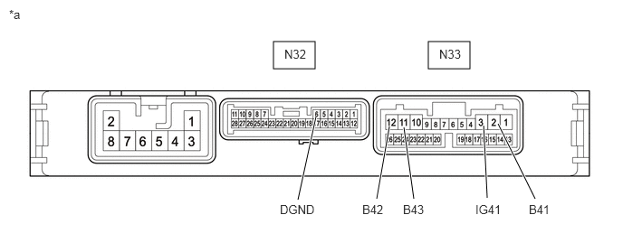
4.927,0.479 5.406,0.792 0.479,0.313 3.146,0.479 3.625,0.792 0.479,0.313 3.427,2.302 3.635,1.344 true 4.333,2.292 4.479,1.458 true 5.604,2.281 5.563,1.448 true 6.156,2.292 5.729,1.427 true 4.76,2.292 4.646,1.469 true 3.219,2.333 3.833,2.531 0.615,0.198 10 false DGND 4.167,2.333 4.781,2.531 0.615,0.198 10 false B42 5.469,2.333 6.083,2.5 0.615,0.167 10 false IG41 6.083,2.333 6.698,2.531 0.615,0.198 10 false B41 3.271,0.542 3.729,0.74 0.458,0.198 10 false N32 5.052,0.542 5.51,0.74 0.458,0.198 10 false N33 0.104,0.083 0.719,0.281 0.615,0.198 10 false *a 4.635,2.333 5.25,2.531 0.615,0.198 10 false B43
*a Component without harness connected
(Engine Stop and Start ECU)
- -


a.

Disconnect the engine stop and start ECU connectors.


b.

Measure the resistance according to the value(s) in the table below.

Standard Resistance:
Tester Connection Condition Specified Condition
N33-2 (B41) - N32-6 (DGND) Always 10 kΩ or higher
N33-3 (IG41) - N32-6 (DGND) Always 10 kΩ or higher
N33-11 (B43) - N32-6 (DGND) Always 10 kΩ or higher
N33-12 (B42) - N32-6 (DGND) Always 10 kΩ or higher


Result:
Proceed to
OK
NG


OK

5.CHECK VEHICLE CONDITION (B41, B42, B43 OR IG41 CIRCUIT)

NG

5.CHECK VEHICLE CONDITION (B41, B42, B43 OR IG41 CIRCUIT)
a.

Check that additional devices installed to the vehicle (aftermarket audio system, etc.) are not connected to the B41, B42, B43 or IG41 terminal circuit of the engine stop and start ECU.

Result:
Result Proceed to
Load from an additional device installed to the vehicle (aftermarket audio system, etc.) is not applied. A
Load from an additional device installed to the vehicle (aftermarket audio system, etc.) is applied. B


A

TROUBLESHOOT ECUS CONNECTED TO TERMINALS B41, B42, B43 AND IG41

B

END (REMOVE ADDITIONAL DEVICE)