HEATING / AIR CONDITIONING FRONT AIR CONDITIONING UNIT(for RHD) REASSEMBLY
CAUTION / NOTICE / HINT
- HINT:
-
A bolt without a torque specification is shown in the standard bolt chart.
PROCEDURE

 87114B
1.INSTALL HEATER COVER (w/o PTC Heater)
87114B
1.INSTALL HEATER COVER (w/o PTC Heater)
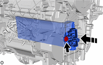

|
Install in this Direction |
Install the heater cover with the screw.
87710G
2.INSTALL QUICK HEATER ASSEMBLY (w/ PTC Heater)
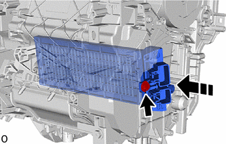
|
|
Install in this Direction |
Install the quick heater assembly with the screw.
- NOTICE:
-
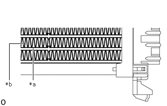 0.677,1.646 0.677,1 true 0.188,1.646 0.188,0.896 0.188,0.896 0.5,0.896 true 0.604,1.667 0.917,1.865 0.313,0.198 10 false *a 0.115,1.667 0.427,1.865 0.313,0.198 10 false *b
*a Element *b Fin
- ·
Do not hold the quick heater assembly by the element or fin. Also, do not damage the quick heater assembly.
·Foul odors may occur due to oil adhering to the quick heater assembly.
88625
3.INSTALL NO. 1 COOLER THERMISTOR (FRONT EVAPORATOR TEMPERATURE SENSOR)
88501
4.INSTALL NO. 1 COOLER EVAPORATOR SUB-ASSEMBLY
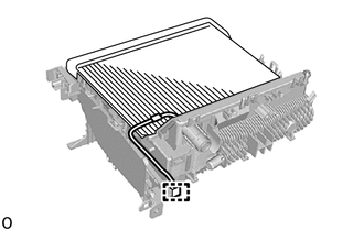
Install the No. 1 cooler evaporator sub-assembly together with the No. 1 cooler thermistor to the upper heater case.
Connect the connector clamp to the upper heater case.
Attach the guide to temporarily install the upper heater case to the lower heater case.
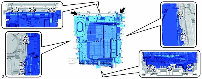
Attach the claw to install the upper heater case to the lower heater case.
Install the 2 screws.
87212
5.INSTALL REAR NO. 1 AIR DUCT (w/ Rear Foot Duct, w/ Center Foot Duct)
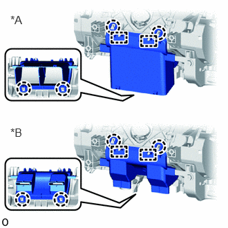
| *A | w/ Rear Foot Duct |
| *B | w/ Center Foot Duct |
Attach the guide and claw to install the rear No. 1 air duct.
87211X
6.INSTALL BLOWER COVER (w/o Center Foot Duct, Rear Foot Duct)
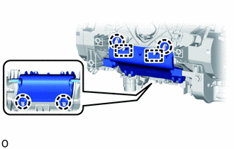
Attach the guide and claw to install the blower cover.
88515
7.INSTALL COOLER EXPANSION VALVE
Remove the vinyl tape from the No. 1 cooler evaporator sub-assembly and cooler expansion valve.
Sufficiently apply compressor oil to 2 new O-rings and the fitting surface of the No. 1 cooler evaporator sub-assembly.
- Compressor oil:
ND-OIL 8 or equivalent
Install the 2 O-rings to the No. 1 cooler evaporator sub-assembly.
- NOTICE:
-
Keep the O-rings and O-ring fitting surfaces free of foreign matter.
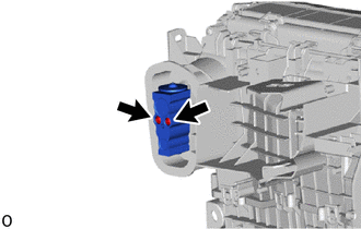
Using a 4 mm hexagon socket wrench, install the cooler expansion valve with the 2 bolts.
- Torque:
- 3.5 N*m (36 kgf*cm, 31 in.*lbf)
- NOTICE:
-
Make sure not to cut the O-ring while installing it (Cut O-rings cannot be installed).
88899L
8.INSTALL COOLING UNIT PARTS
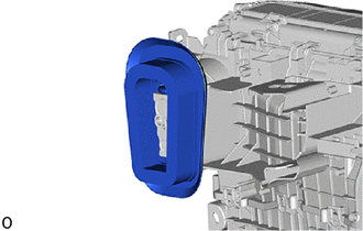
Install the cooling unit parts.
88482
9.INSTALL COOLER CAP (w/o Cooler System)
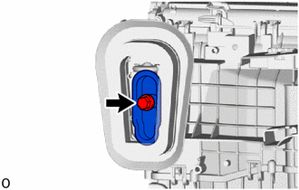
Install the cooler cap with the bolt.
87107A
10.INSTALL HEATER RADIATOR UNIT SUB-ASSEMBLY (w/ Heater System)
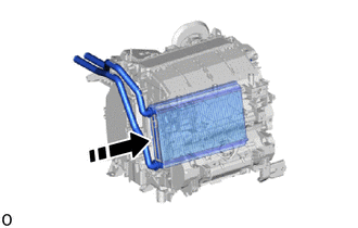
|
|
Install in this Direction |
Install the heater radiator unit sub-assembly shown in the illustration.
87124B
11.INSTALL HEATER CLAMP (w/ Heater System)
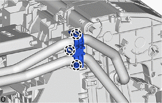
Attach the claw to install the heater clamp.
87128
12.INSTALL HEATER GROMMET
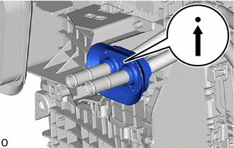
Install the heater grommet as shown in the illustration.
- NOTICE:
-
Install the heater grommet with the arrow facing up.
13.INSTALL NO. 2 HEATER CONTROL CABLE SUB-ASSEMBLY (except Automatic Air Conditioning System)
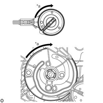
| *a | FACE |
Set the cable gear and unit link to the FACE position.
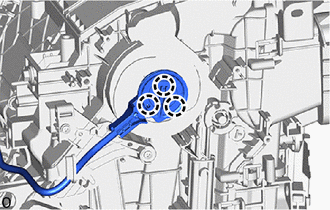
Attach the claw to install the No. 2 heater control cable sub-assembly.
14.INSTALL AIR MIX DAMPER CONTROL CABLE SUB-ASSEMBLY (except Automatic Air Conditioning System)
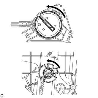
| *a | MAX COOL |
Set the cable gear and unit gear to the MAX COOL position.
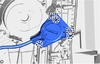
Attach the guide and claw to install the air mix damper control cable sub-assembly.
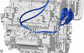
Attach the guide to install each cable.
87050C
15.INSTALL NO. 1 AIR CONDITIONING RADIATOR DAMPER SERVO SUB-ASSEMBLY (for Automatic Air Conditioning System)
Align each gear on the air conditioner radiator assembly side as shown in the illustration, and then check that the gears of the No. 1 air conditioning radiator damper servo sub-assembly are aligned as shown in the illustration.
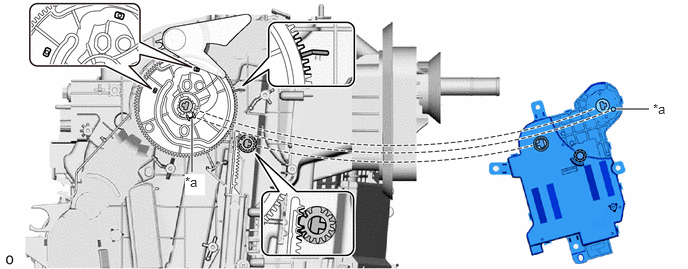
| *a | Gear Alignment Part | - | - |
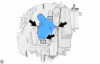
Attach the guide and install the No. 1 air conditioning radiator damper servo sub-assembly with the 3 screws.
82210K
16.INSTALL AIR CONDITIONING HARNESS ASSEMBLY (for Automatic Air Conditioning System)
Attach the guide to install the air conditioning harness assembly.
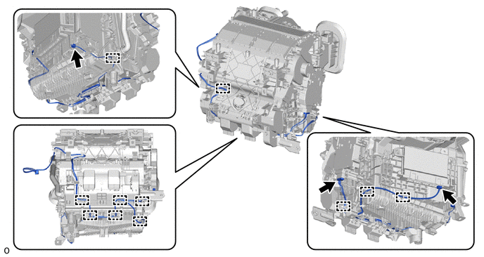
Connect the 3 connectors.
88897P
17.INSTALL ASPIRATOR (for Automatic Air Conditioning System)
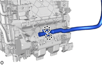
Attach the claw to install the aspirator.
87130D
18.INSTALL BLOWER ASSEMBLY
87211A
19.INSTALL NO. 2 AIR DUCT
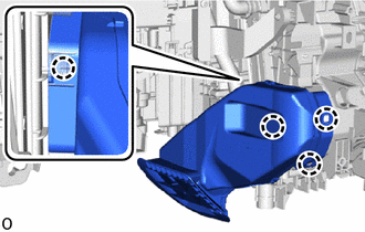
Attach the claw to install the No. 2 air duct.
- NOTICE:
- ·
When removing, do not crack or deform the lower heater case of the air conditioning radiator assembly.
·If the No. 2 air duct is reused, it may fall off or abnormal noise may occur. Therefore, make sure to replace with a new one.
88649
20.INSTALL NO. 2 COOLER WIRING (w/ PTC Heater)
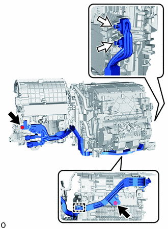

|
Screw |

|
Connector |
Attach the guide to install the No. 2 cooler wiring.
Install the 2 screws.
Connect the 2 connectors.
5538E
21.INSTALL ELECTRICAL PARTS MOUNTING BRACKET
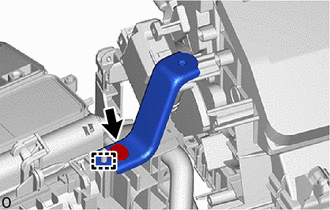
Attach the guide and install the electrical parts mounting bracket with the screw.
55990B
22.INSTALL LOWER DEFROSTER NOZZLE ASSEMBLY
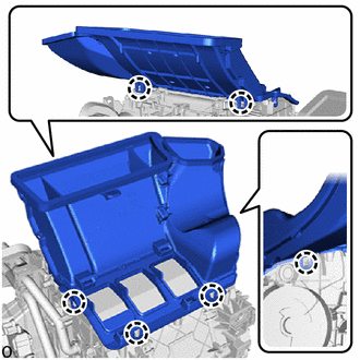
Attach the claw to install the lower defroster nozzle assembly.