HEATING / AIR CONDITIONING REAR AIR CONDITIONING UNIT REASSEMBLY
PROCEDURE

 88726E
1.INSTALL COOLER REFRIGERANT LIQUID PIPE E
88726E
1.INSTALL COOLER REFRIGERANT LIQUID PIPE E
Remove the vinyl tape from the cooler refrigerant liquid pipe E.
Sufficiently apply compressor oil to 2 new O-rings and the fitting surfaces of the cooler refrigerant liquid pipe E.
- Compressor oil:
ND-OIL 8 or equivalent
Install the 2 O-rings to the cooler refrigerant liquid pipe E.
- NOTICE:
-
Keep the O-rings and O-ring fitting surfaces free of foreign matter.
88515A
2.INSTALL REAR COOLING UNIT EXPANSION VALVE
Remove the vinyl tape from the rear cooling unit expansion valve.
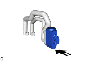

|
Install in this Direction |
Install the rear cooling unit expansion valve in the direction indicated by the arrow as shown in the illustration.
- NOTICE:
-
Make sure not to cut the O-ring while installing it. (Cut O-rings cannot be installed)
88727E
3.INSTALL COOLER REFRIGERANT SUCTION PIPE E
Remove the vinyl tape from the cooler refrigerant suction pipe E.
Sufficiently apply compressor oil to 2 new O-rings and the fitting surfaces of the cooler refrigerant suction pipe E.
- Compressor oil:
ND-OIL 8 or equivalent
Install the 2 O-rings to the cooler refrigerant suction pipe E.
- NOTICE:
-
Keep the O-rings and O-ring fitting surfaces free of foreign matter.
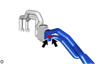
Install the cooler refrigerant suction pipe E with the 2 bolts.
- Torque:
- 5.4 N*m (55 kgf*cm, 48 in.*lbf)
- NOTICE:
-
Make sure not to cut the O-ring while installing it. (Cut O-rings cannot be installed)
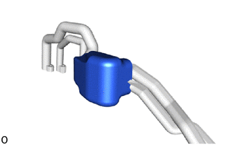
Install a new cooling unit packing.
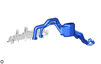
Install the cooler refrigerant suction pipe E with cooler refrigerant liquid pipe E to the cover RH.
87248F
4.INSTALL HEATER WATER INLET PIPE F
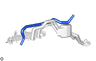
Install the heater water inlet pipe F to the cover RH.
87249G
5.INSTALL HEATER WATER OUTLET PIPE G
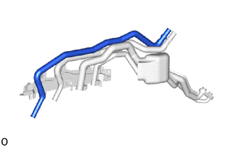
Install the heater water outlet pipe G to the cover RH.
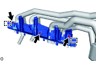
Attach the guide to install the cover LH.
Install the 3 screws.
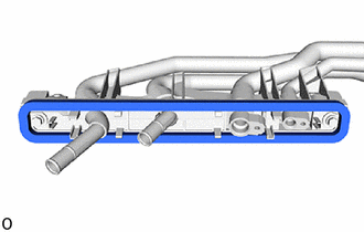
Install a new packing.
6.INSTALL PIPING CLAMP
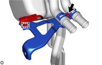
Install the piping clamp with the screw.
Attach the clamp.
87246
7.INSTALL HEATER WATER HOSE OUTLET
Using pliers, grip the claws of the clip and slide the clip to install the heater water hose outlet.
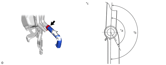
| *a | Outlet Hose Installation Angle / 147.9° | *b | Outlet Hose Clip Installation Angle / 148.4° to 208.4° |
| *c | View A | - | - |
87245H
8.INSTALL HEATER WATER HOSE INLET H
Using pliers, grip the claws of the clip and slide the clip to install the heater water hose inlet H.
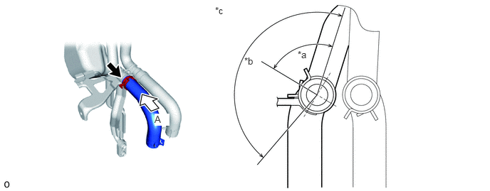
| *a | Inlet Hose Clip Installation Angle / 46.4° to 106.4° | *b | Inlet Hose Installation Angle / 157.5° |
| *c | View A | - | - |
88605C
9.INSTALL NO. 2 AIR CONDITIONING HARNESS ASSEMBLY
- HINT:
-
If damaged during removal, replace the part with a new one.

|
|
Install in this Direction |
Attach the claw to install the No. 2 air conditioning harness assembly.
88501R
10.INSTALL REAR EVAPORATOR SUB-ASSEMBLY
Remove the vinyl tape from the rear evaporator sub-assembly.
Sufficiently apply compressor oil to 2 new O-rings and the fitting surface of the rear evaporator sub-assembly.
- Compressor oil:
ND-OIL 8 or equivalent
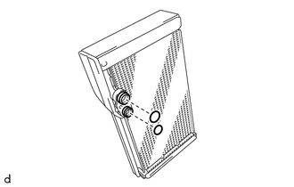
Install the 2 O-rings to the rear evaporator sub-assembly.
- NOTICE:
-
Keep the O-rings and O-ring fitting surfaces free of foreign matter.
|
|
Install in this Direction |
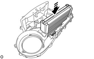
Install the rear evaporator sub-assembly in the direction indicated by the arrow as shown in the illustration.
Attach the claw and guide to install the heater case LH.
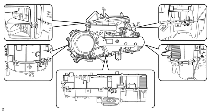
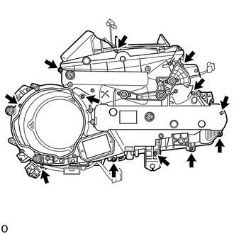
Install the heater case LH with the 12 screws.
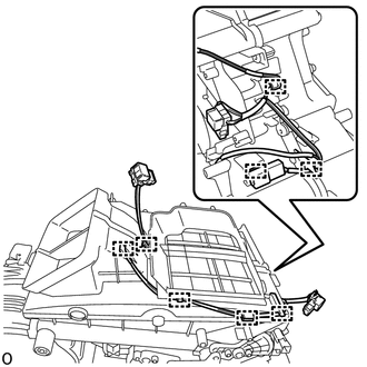
Attach the clamp to connect the wire harness.
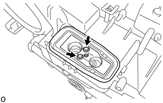
Remove the vinyl tape from the connector tube.
Using a 4 mm hexagon socket wrench, install the connector tube with the 2 bolts.
- Torque:
- 3.5 N*m (36 kgf*cm, 31 in.*lbf)
- NOTICE:
-
Make sure not to cut the O-ring while installing it. (Cut O-rings cannot be installed)
Install the grommet.
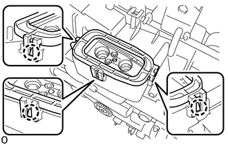
Attach the claw to install the plate.
88539K
11.INSTALL DRAIN COOLER HOSE
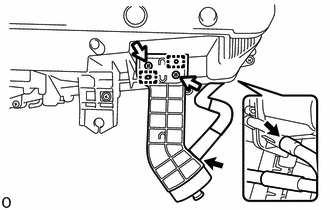
Attach the guide to install the drain cooler hose.
Install the 2 screws.
Align the protrusion on the rear cooling unit case RH with the indentation on the drain cooler hose, and install the drain cooler hose.
12.INSTALL WIRE HARNESS
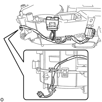
Attach the clamp to install the wire harness.
87107B
13.INSTALL HEATER RADIATOR UNIT SUB-ASSEMBLY
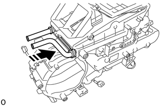
|
|
Install in this Direction |
Install the heater radiator unit sub-assembly in the direction indicated by the arrow as shown in the illustration.
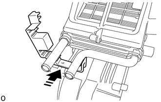
|
|
Install in this Direction |
Install the heater unit clamp in the direction indicated by the arrow as shown in the illustration.
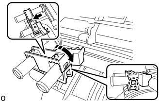
|
|
Install in this Direction |
Attach the claw to install the radiator heater unit clamp in the direction indicated by the arrow as shown in the illustration.
Install the screw.
88710E
14.INSTALL AIR CONDITIONING TUBE AND ACCESSORY ASSEMBLY
Remove the vinyl tape from the air conditioning tube and accessory assembly.
Sufficiently apply compressor oil to 2 new O-rings and the fitting surfaces of the air conditioning tube and accessory assembly.
- Compressor oil:
ND-OIL 8 or equivalent
Install the 2 O-rings to the air conditioning tube and accessory assembly.
- NOTICE:
-
Keep the O-rings and O-ring fitting surfaces free of foreign matter.
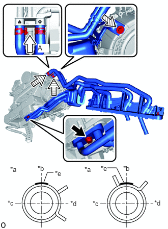
| *a | View A |
| *b | Upper Side |
| *c | RH Side |
| *d | LH Side |
| *e | White Marking |

|
Bolt |

|
Hose Clip |

|
Screw |
Install the air conditioning tube and accessory assembly with the bolt.
- Torque:
- 5.4 N*m (55 kgf*cm, 48 in.*lbf)
- NOTICE:
-
Make sure not to cut the O-ring while installing it. (Cut O-rings cannot be installed)
Using pliers, grip the claws of the clip and slide the clip to install the heater water hose inlet C and heater water hose outlet C.
Install the screw.
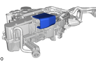
Install a new No. 1 cooling unit packing.
87165C
15.INSTALL BLOWER MOTOR CONTROL
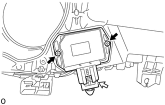
|
|
Screw |

|
Connector |
Install the blower motor control with the 2 screws.
Connect the connector.
87103D
16.INSTALL REAR BLOWER WITH FAN MOTOR SUB-ASSEMBLY
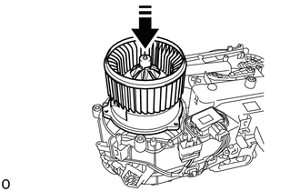
|
|
Install in this Direction |
Install the rear blower with fan motor sub-assembly in the direction indicated by the arrow as shown in the illustration.
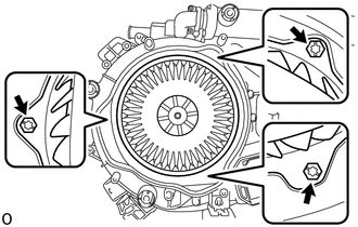
Install the 3 screws.
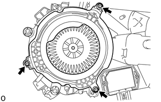
Install the plate with the 3 screws.
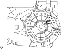
Connect the connector.
88688Z
17.INSTALL BRACKET
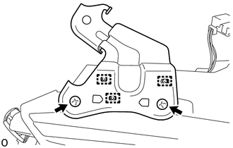
Attach the guide to install the bracket.
Install the 2 screws
87030F
18.INSTALL REAR NO. 2 COOLING UNIT DAMPER SERVO SUB-ASSEMBLY
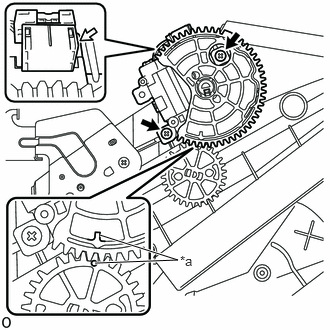
| *a | Align as shown |
|
|
Screw |
|
|
Connector |
Align each gear on the rear air conditioning blower assembly side as shown in the illustration, and then check that the gears of the rear No. 2 cooling unit damper servo sub-assembly are aligned as shown in the illustration.
Install the rear No. 2 cooling unit damper servo sub-assembly with the 2 screws.
Connect the connector.
87030E
19.INSTALL REAR NO. 1 COOLING UNIT DAMPER SERVO SUB-ASSEMBLY
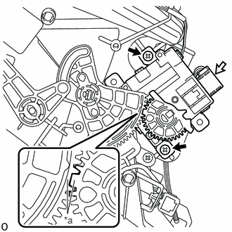
| *a | Align as shown |
|
|
Screw |
|
|
Connector |
Align each gear on the rear air conditioning blower assembly side as shown in the illustration, and then check that the gears of the rear No. 1 cooling unit damper servo sub-assembly are aligned as shown in the illustration.
Install the rear No. 1 cooling unit damper servo sub-assembly with the 2 screws.
Connect the connector.
87212C
20.INSTALL REAR AIR DUCT
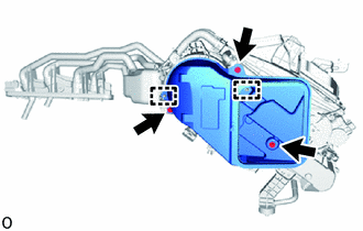
Attach the guide to install the rear air duct.
Install the 3 screws.
87220
21.INSTALL AIR DUCT ASSEMBLY
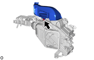
Install the air duct assembly with the screw.