LIGHTING (INT) PERSONAL LIGHT(for Wagon) INSPECTION
PROCEDURE

 81208
1.INSPECT MAP LIGHT SUB-ASSEMBLY (w/o Telematics Transceiver)
81208
1.INSPECT MAP LIGHT SUB-ASSEMBLY (w/o Telematics Transceiver)
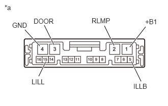
| *a | Component without harness connected
(Map Light Sub-assembly) |
Check the map light.
Measure the resistance according to the value(s) in the table below.
- Standard Resistance:
Tester Connection Switch Condition Specified Condition 1 (+B1) - 4 (GND) Map light switch LH OFF 10 kΩ or higher Map light switch LH ON Below 1 Ω Map light switch RH OFF 10 kΩ or higher Map light switch RH ON Below 1 Ω Dome light switch OFF 10 kΩ or higher Dome light switch ON Below 1 Ω 1 (+B1) - 3 (DOOR) Door Switch OFF 10 kΩ or higher Door Switch ON Below 1 Ω
If the result is not as specified, replace the map light sub-assembly.
Check the door switch.
Measure the resistance according to the value(s) in the table below.
- Standard Resistance:
Tester Connection Switch Condition Specified Condition 3 (DOOR) - 2 (RLMP) Door Switch OFF 10 kΩ or higher Door Switch ON Below 1 Ω
If the result is not as specified, replace the map light sub-assembly.
Inspect the switch illumination.
Apply battery voltage to the connector and check the light illumination condition.
- OK:
Measurement Condition Condition Specified Condition Battery positive (+) → 5 (ILLB)
Battery negative (-) → 15 (LILL)Always Switch illumination comes on
If the result is not as specified, replace the map light sub-assembly.
81208
2.INSPECT MAP LIGHT SUB-ASSEMBLY (w/ Telematics Transceiver)
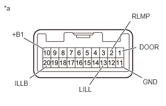
| *a | Component without harness connected
(Map Light Sub-assembly) |
Check the map light.
Measure the resistance according to the value(s) in the table below.
- Standard Resistance:
Tester Connection Switch Condition Specified Condition 10 (+B1) - 11 (GND) Map light switch LH OFF 10 kΩ or higher Map light switch LH ON Below 1 Ω Map light switch RH OFF 10 kΩ or higher Map light switch RH ON Below 1 Ω Dome light switch OFF 10 kΩ or higher Dome light switch ON Below 1 Ω 10 (+B1) - 1 (DOOR) Door Switch OFF 10 kΩ or higher Door Switch ON Below 1 Ω
If the result is not as specified, replace the map light sub-assembly.
Check the door switch.
Measure the resistance according to the value(s) in the table below.
- Standard Resistance:
Tester Connection Switch Condition Specified Condition 1 (DOOR) - 2 (RLMP) Door Switch OFF 10 kΩ or higher Door Switch ON Below 1 Ω
If the result is not as specified, replace the map light sub-assembly.
Inspect the switch illumination.
Apply battery voltage to the connector and check the light illumination condition.
- OK:
Measurement Condition Condition Specified Condition Battery positive (+) → 20 (ILLB)
Battery negative (-) → 13 (LILL)Always Switch illumination comes on
If the result is not as specified, replace the map light sub-assembly.