INTERIOR PANELS / TRIM ROOF HEADLINING(for Wagon) REASSEMBLY
CAUTION / NOTICE / HINT
- HINT:
- ·
Use the same procedure for RHD and LHD vehicles.
·The procedure listed below is for LHD vehicles.
PROCEDURE

 63415D
1.INSTALL CENTER ROOF SPEAKER GRILLE
63415D
1.INSTALL CENTER ROOF SPEAKER GRILLE
- HINT:
-
Use the same procedure for both center roof speaker grilles.
for 6 Speakers:
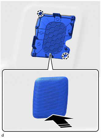

|
Install in this Direction |
Attach the claw to install the center roof speaker grille.
for 12 Speakers:
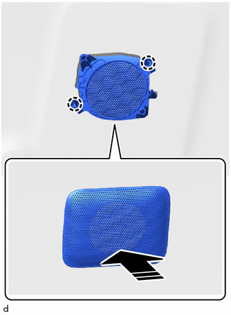
|
|
Install in this Direction |
Attach the claw to install the center roof speaker grille.
63610
2.INSTALL NO. 1 AIR OUTLET REGISTER ASSEMBLY
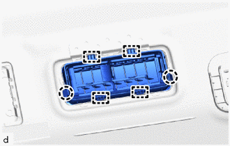
Attach the claw and guide to install the No. 1 air outlet register assembly.
63620
3.INSTALL NO. 2 AIR OUTLET REGISTER ASSEMBLY
- HINT:
-
Use the same procedure for No. 1 air outlet register assembly.
82173
4.INSTALL NO. 3 ROOF WIRE
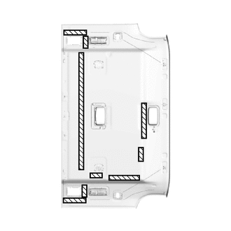

|
Butyl Tape |
Apply butyl tape as shown in the illustration.
- HINT:
-
Place the tape securely so that it is not misaligned or peeling.
w/ Curtain Shield Airbag:
Install the No. 3 roof wire to the double-sided butyl tape as shown in the illustration and secure the No. 3 roof wire with pieces of fastening tape.
- HINT:
-
Align the tape with the markings when attaching it.
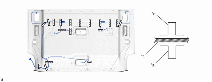
| *1 | No. 3 Roof Wire | - | - |
| *a | Marking | - | - |
|
|
Tape | - | - |
w/o Curtain Shield Airbag:
Install the No. 3 roof wire to the double-sided butyl tape as shown in the illustration and secure the No. 3 roof wire with pieces of fastening tape.
- HINT:
-
Align the tape with the markings when attaching it.
Attach the clamp.
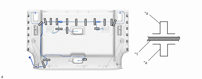
| *1 | No. 3 Roof Wire | - | - |
| *a | Marking | - | - |
|
|
Tape | - | - |
w/ Rear Air Conditioning System:
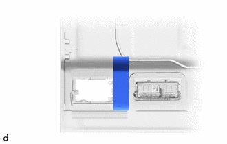
Install the air duct packing.
- HINT:
-
Use the same procedure for the opposite side.
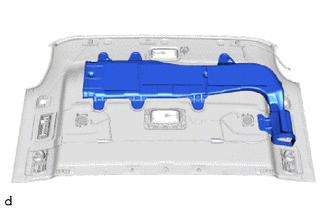
Install the air duct with hot-melt glue.
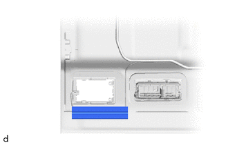
Install the No. 10 silencer pad.
- HINT:
-
Use the same procedure for the opposite side.
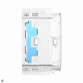

|
Marking |
Align the markings on the roof headlining assembly with the silencer pad and install them using hot-melt glue as shown in the illustration.
74605A
5.INSTALL COAT HOOK SUB-ASSEMBLY
- HINT:
-
Use the same procedure for both coat hook sub-assemblies.
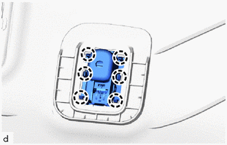
Attach the claw to install the coat hook sub-assembly.
86150A
6.INSTALL NO. 2 ROOF SPEAKER ASSEMBLY WITH BRACKET (for 6 Speakers, Front Side)
86160Q
7.INSTALL ROOF SPEAKER ASSEMBLY (for 12 Speakers, Front Side)
81360T
8.INSTALL SPOT LIGHT ASSEMBLY (for Rear Side)
63416B
9.INSTALL ROOF SPEAKER GRILLE LH (for 12 Speakers)
|
|
Install in this Direction |
Attach the claw to install the roof speaker grille LH.
63415B
10.INSTALL ROOF SPEAKER GRILLE RH (for 12 Speakers)
- HINT:
-
Use the same procedure described for the LH side.
63388A
11.INSTALL ROOF HEADLINING HOLDER COVER
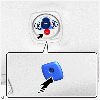
|
|
Install in this Direction |
Attach the claw to install the roof headlining holder cover.
Install the screw.
63610H
12.INSTALL NO. 3 AIR OUTLET REGISTER ASSEMBLY (w/ Rear Cooler)
- HINT:
-
Use the same procedure for No. 1 air outlet register assembly.
63640A
13.INSTALL NO. 4 AIR OUTLET REGISTER ASSEMBLY (w/ Rear Cooler)
- HINT:
-
Use the same procedure for No. 1 air outlet register assembly.
82172
14.INSTALL NO. 2 ROOF WIRE
w/ Rear Cooler:
Apply butyl tape as shown in the illustration.
- HINT:
-
Place the tape securely so that it is not misaligned or peeling.
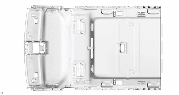
|
|
Butyl Tape | - | - |
Attach each clamp.
Install the No. 2 roof wire to the double-sided butyl tape as shown in the illustration and secure the No. 2 roof wire with pieces of fastening tape.
- HINT:
-
Align the tape with the markings when attaching it.
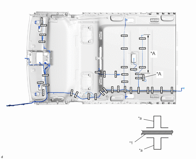
| *A | for 12 Speakers | - | - |
| *1 | No. 2 Roof Wire | - | - |
| *a | Marking | - | - |
|
|
Tape | - | - |
w/ Rear Air Conditioning System:
Apply butyl tape as shown in the illustration.
- HINT:
-
Place the tape securely so that it is not misaligned or peeling.
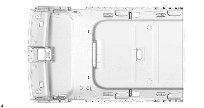
|
|
Butyl Tape | - | - |
Attach each clamp.
Install the No. 2 roof wire to the double-sided butyl tape as shown in the illustration and secure the No. 2 roof wire with pieces of fastening tape.
- HINT:
-
Align the tape with the markings when attaching it.
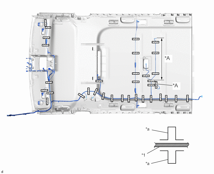
| *A | for 12 Speakers | - | - |
| *1 | No. 2 Roof Wire | - | - |
| *a | Marking | - | - |
|
|
Tape | - | - |
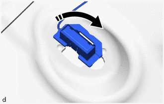
|
|
Install in this Direction |
Turn the visor connectors approximately 90° clockwise to install them to the roof headlining.

|
|
Marking |
Align the markings on the roof headlining assembly with the silencer pad and install them using hot-melt glue as shown in the illustration.
86160Q
15.INSTALL ROOF SPEAKER ASSEMBLY (for 12 Speakers, Rear Side)
88051C
16.INSTALL NO. 2 ION GENERATOR SUB-ASSEMBLY
87202F
17.INSTALL REAR AIR DUCT SUB-ASSEMBLY
84010A
18.INSTALL INTEGRATION CONTROL AND PANEL ASSEMBLY
81360T
19.INSTALL SPOT LIGHT ASSEMBLY (for Front Side)
20.INSTALL WASHER HOSE ASSEMBLY
w/ Rear Cooler:
Fix the washer hose assembly in place with tape as shown in the illustration.
- HINT:
-
Align the tape with the markings when attaching it.
Attach the clamp.
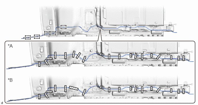
| *A | w/o Curtain Shield Airbag | *B | w/ Curtain Shield Airbag |
|
|
Tape | - | - |
w/ Rear Air Conditioning System:
Fix the washer hose assembly in place with tape as shown in the illustration.
- HINT:
-
Align the tape with the markings when attaching it.
Attach the clamp.
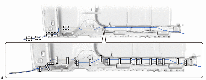
|
|
Tape | - | - |
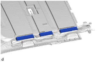
w/ Air Duct Packing:
Install the 3 air duct packings with adhesive or double-sided tape.
867C1
21.INSTALL MIRROR CAMERA WIRE
w/ Rear Cooler:
Fix the mirror camera wire in place with tape as shown in the illustration.
- HINT:
-
Align the tape with the markings when attaching it.
Attach the clamp.
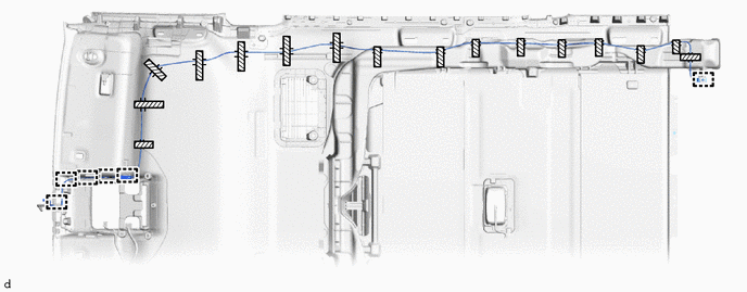
|
|
Tape | - | - |
w/ Rear Air Conditioning System:
Fix the mirror camera wire in place with tape as shown in the illustration.
- HINT:
-
Align the tape with the markings when attaching it.
Attach the clamp.
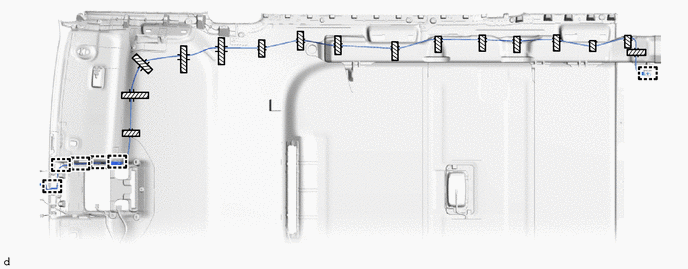
|
|
Tape | - | - |
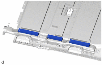
w/ Air Duct Packing:
Install the 3 air duct packings with adhesive or double-sided tape.
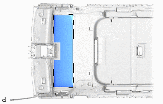
|
|
Marking |
Align the markings on the roof headlining assembly with the silencer pad and install them using hot-melt glue as shown in the illustration.
81340
22.INSTALL VANITY LIGHT ASSEMBLY
- HINT:
-
Use the same procedure for both vanity light assemblies.
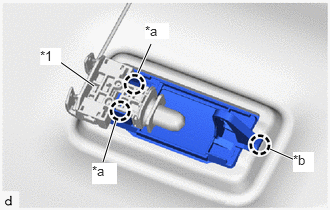
| *1 | Bulb Holder |
| *a | Claw A |
| *b | Claw B |
Attach claw B of the vanity light assembly to temporarily install the vanity light assembly to the roof headlining assembly.
Attach claw A of the bulb holder to install the vanity light assembly.
62821B
23.INSTALL ROOM VENTILATION GRILLE (w/ Rear Air Conditioning System)
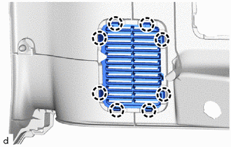
Attach the claw to install the room ventilation grille.
62933H
24.INSTALL QUARTER PANEL AIR INLET DUCT (w/ Rear Air Conditioning System)
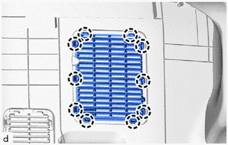
Attach the claw to install the quarter panel air inlet duct.
62932F
25.INSTALL NO. 2 QUARTER VENT DUCT (w/ Rear Air Conditioning System)
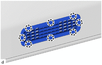
Attach the claw to install the No. 2 quarter vent duct.
62931F
26.INSTALL QUARTER VENT DUCT (w/ Rear Air Conditioning System)
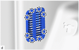
Attach the claw to install the quarter vent duct.
62821B
27.INSTALL ROOM VENTILATION GRILLE (w/ Rear Cooler)
- HINT:
-
Use the same procedure for room ventilation grille.
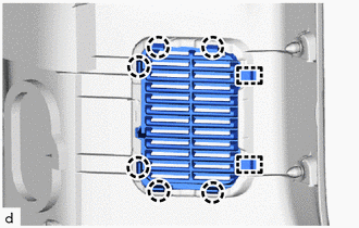
Attach the claw and guide to install the room ventilation grille.
71397H
28.INSTALL REAR SEAT STOPPER LH
71397G
29.INSTALL REAR SEAT STOPPER RH
- HINT:
-
Use the same procedure described for the LH side.
85532D
30.INSTALL NO. 3 USB CHARGER SOCKET
88625C
31.INSTALL COOLER THERMISTOR
81080V
32.INSTALL NO. 2 INTERIOR ILLUMINATION LIGHT ASSEMBLY
81080M
33.INSTALL NO. 1 INTERIOR ILLUMINATION LIGHT ASSEMBLY
- HINT:
-
Use the same procedure for No. 2 interior illumination light assembly.
65992C
34.INSTALL REAR WINDOW CURTAIN LH (w/ Rear Sunshade)
65991E
35.INSTALL REAR WINDOW CURTAIN RH (w/ Rear Sunshade)
65988A
36.INSTALL SUNSHADE HOOK (w/ Rear Sunshade)
- HINT:
-
Use the same procedure for both sunshade hooks.
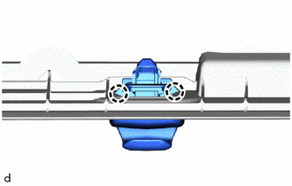
Attach the claw to install the sunshade hook.