SEAT POWER SEAT SWITCH(for Rear Seat) INSPECTION
PROCEDURE

 84923
1.INSPECT REAR POWER SEAT SWITCH (for LH Side, w/o Seat Heater System)
84923
1.INSPECT REAR POWER SEAT SWITCH (for LH Side, w/o Seat Heater System)
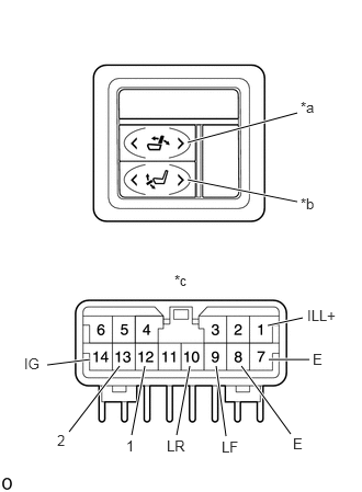
| *a | Reclining Switch |
| *b | Ottoman Switch |
| *c | Component without harness connected
(Rear Power Seat Switch) |
Measure the resistance according to the value(s) in the table below.
- Standard Resistance:
Reclining Switch Tester Connection Switch Condition Specified Condition 14 (IG) - 9 (LF)
10 (LR) - 8 (E)Front position Below 1 Ω 9 (LF) - 8 (E)
10 (LR) - 8 (E)Neutral 14 (IG) - 10 (LR)
9 (LF) - 8 (E)Rear position
Ottoman Switch Tester Connection Switch Condition Specified Condition 14 (IG) - 12 (1)
13 (2) - 8 (E)Up position Below 1 Ω 12 (1) - 8 (E)
13 (2) - 8 (E)Neutral 14 (IG) - 13 (2)
12 (1) - 8 (E)Down position
If the result is not as specified, replace the rear power seat switch.
Apply battery voltage to the switch connector and check that the rear power seat switch illuminates.
- OK:
Measurement Condition Specified Condition Battery positive (+) - Terminal 1 (ILL+)
Battery negative (-) - Terminal 7 (E)Illumination illuminates
If the result is not as specified, replace the rear power seat switch.
84923
2.INSPECT REAR POWER SEAT SWITCH (for RH Side, w/o Seat Heater System)
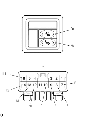
| *a | Reclining Switch |
| *b | Ottoman Switch |
| *c | Component without harness connected
(Rear Power Seat Switch) |
Measure the resistance according to the value(s) in the table below.
- Standard Resistance:
Reclining Switch Tester Connection Switch Condition Specified Condition 14 (IG) - 13 (M)
12 (NF) - 8 (E)Front position Below 1 Ω 13 (M) - 8 (E)
12 (NF) - 8 (E)Neutral 14 (IG) - 12 (NF)
13 (M) - 8 (E)Rear position
Ottoman Switch Tester Connection Switch Condition Specified Condition 14 (IG) - 10 (1)
9 (2) - 8 (E)Up position Below 1 Ω 10 (1) - 8 (E)
9 (2) - 8 (E)Neutral 14 (IG) - 10 (2)
10 (1) - 8 (E)Down position
If the result is not as specified, replace the rear power seat switch.
Apply battery voltage to the switch connector and check that the rear power seat switch illuminates.
- OK:
Measurement Condition Specified Condition Battery positive (+) - Terminal 6 (ILL+)
Battery negative (-) - Terminal 7 (E)Illumination illuminates
If the result is not as specified, replace the rear power seat switch.
84923
3.INSPECT REAR POWER SEAT SWITCH (for LH Side, w/ Seat Heater System)
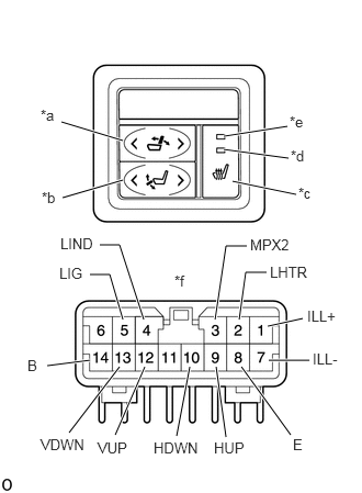
| *a | Reclining Switch |
| *b | Ottoman Switch |
| *c | Seat Heater Switch |
| *d | Seat Heater Indicator Light (1) |
| *e | Seat Heater Indicator Light (2) |
| *f | Component without harness connected
(Rear Power Seat Switch) |
Measure the resistance according to the value(s) in the table below.
- Standard Resistance:
Reclining Switch Tester Connection Switch Condition Specified Condition 14 (B) - 9 (HUP)
10 (HDWN) - 8 (E)Front position Below 1 Ω 9 (HUP) - 8 (E)
10 (HDWN) - 8 (E)Neutral 14 (B) - 10 (HDWN)
9 (HUP) - 8 (E)Rear position
Ottoman Switch Tester Connection Switch Condition Specified Condition 14 (B) - 12 (VUP)
13 (VDWN) - 8 (E)Up position Below 1 Ω 12 (VUP) - 8 (E)
13 (VDWN) - 8 (E)Neutral 14 (B) - 13 (VDWN)
12 (VUP) - 8 (E)Down position
Seat Heater Switch Tester Connection Switch Condition Specified Condition 2 (LHTR) - 8 (E) ON Below 1 Ω OFF 10 kΩ or higher
If the result is not as specified, replace the rear power seat switch.
Apply battery voltage to the switch connector and check that the rear power seat switch illuminates.
- OK:
Measurement Condition Specified Condition Battery positive (+) - Terminal 1 (ILL+)
Battery negative (-) - Terminal 7 (ILL-)Illumination illuminates
If the result is not as specified, replace the rear power seat switch.
Apply battery voltage to the switch connector and check that the Seat Heater Indicator Light.
- OK:
Measurement Condition Specified Condition Battery positive (+) - Terminal 5 (LIG)
Battery negative (-) - Terminal 4 (LIND)Seat heater indicator light (1) illuminates Battery positive (+) - Terminal 5 (LIG)
Battery negative (-) - Terminal 3 (MPX2)Seat heater indicator light (2) illuminates
If the result is not as specified, replace the rear power seat switch.
84923
4.INSPECT REAR POWER SEAT SWITCH (for RH Side, w/ Seat Heater System)
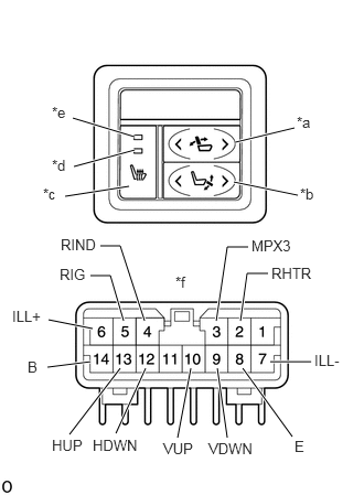
| *a | Reclining Switch |
| *b | Ottoman Switch |
| *c | Seat Heater Switch |
| *d | Seat Heater Indicator Light (1) |
| *e | Seat Heater Indicator Light (2) |
| *f | Component without harness connected
(Rear Power Seat Switch) |
Measure the resistance according to the value(s) in the table below.
- Standard Resistance:
Reclining Switch Tester Connection Switch Condition Specified Condition 14 (B) - 13 (HUP)
12 (HDWN) - 8 (E)Front position Below 1 Ω 13 (HUP) - 8 (E)
12 (HDWN) - 8 (E)Neutral 14 (B) - 12 (HDWN)
13 (HUP) - 8 (E)Rear position
Ottoman Switch Tester Connection Switch Condition Specified Condition 14 (B) - 10 (VUP)
9 (VDWN) - 8 (E)Up position Below 1 Ω 10 (VUP) - 8 (E)
9 (VDWN) - 8 (E)Neutral 14 (B) - 9 (VDWN)
10 (VUP) - 8 (E)Down position
Seat Heater Switch Tester Connection Switch Condition Specified Condition 2 (RHTR) - 8 (E) ON Below 1 Ω OFF 10 kΩ or higher
If the result is not as specified, replace the rear power seat switch.
Apply battery voltage to the switch connector and check that the rear power seat switch illuminates.
- OK:
Measurement Condition Specified Condition Battery positive (+) - Terminal 6 (ILL+)
Battery negative (-) - Terminal 7 (ILL-)Illumination illuminates
If the result is not as specified, replace the rear power seat switch.
Apply battery voltage to the switch connector and check that the Seat Heater Indicator Light.
- OK:
Measurement Condition Specified Condition Battery positive (+) - Terminal 5 (RIG)
Battery negative (-) - Terminal 4 (RIND)Seat heater indicator light (1) illuminates Battery positive (+) - Terminal 5 (RIG)
Battery negative (-) - Terminal 3 (MPX3)Seat heater indicator light (2) illuminates
If the result is not as specified, replace the rear power seat switch.