SEAT REAR SEAT ASSEMBLY(for Power Captain Seat) REASSEMBLY
CAUTION / NOTICE / HINT
- CAUTION:
- ·
Wear protective gloves. Sharp areas on the parts may injure your hands.
·There is risk of injury.
- HINT:
- ·
Use the same procedure for RHD and LHD vehicles.
·The procedures listed below are for LHD vehicles.
·Use the same procedure for the RH and LH sides.
·The procedure listed below is for the LH side.
·The procedure listed below is a representative example.
·Use the same procedure for first row and second row, unless otherwise specified.
PROCEDURE

 79102B
1.INSTALL NO. 1 SEAT CUSHION FRAME SUB-ASSEMBLY LH
79102B
1.INSTALL NO. 1 SEAT CUSHION FRAME SUB-ASSEMBLY LH
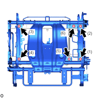
Temporarily install the No. 1 seat cushion frame sub-assembly LH with the 6 nuts in the order shown in the illustration.
Tighten the 6 nuts in the order shown in the illustration.
- Torque:
- 42 N*m (428 kgf*cm, 31 ft.*lbf)
82195B
2.INSTALL REAR SEAT NO. 4 WIRE RH
Attach each clamp and install the rear seat No. 4 wire RH.
82194
3.INSTALL REAR SEAT WIRE LH
Attach each clamp and install the rear seat wire LH.
72210U
4.INSTALL NO. 1 SEAT TRACK CONTROL CABLE ASSEMBLY LH
for First Row:
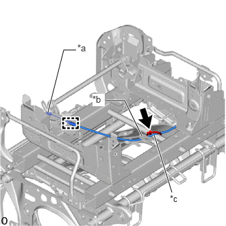
| *a | Cable End |
| *b | Bracket |
| *c | Location Tape (Yellow) |
Attach the cable clamp and cable end and install the No. 1 seat track control cable assembly LH as shown in the illustration.
- NOTICE:
-
Pass the No. 1 seat track control cable assembly LH under the bracket as shown in the illustartion.
- HINT:
-
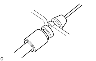
-
Install at the middle level of the cable clamp (triple level) side.
Install a new cable tie.
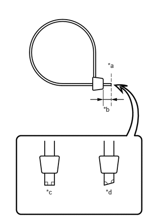
| *a | Cut Here |
| *b | 5 mm (0.197 in.) to 10 mm (0.394 in.) |
| *c | Correct |
| *d | Incorrect |
Cut off the end of the cable tie as shown in the illustration.
- HINT:
-
Make sure that the end of the cable tie faces below.
for Second Row:
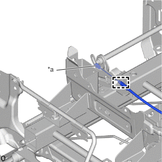
| *a | Cable End |
Attach the cable clamp and cable end and install the No. 1 seat track control cable assembly LH as shown in the illustration.
- HINT:
-
-
Install at the middle level of the cable clamp (triple level) side.
72210R
5.INSTALL NO. 1 SEAT SLIDE CABLE ASSEMBLY LH
for First Row:
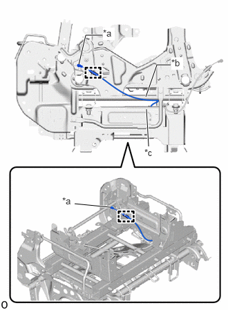
| *a | Cable End |
| *b | Pipe |
| *c | Frame |
Attach the cable clamp and cable end and install the No. 1 seat slide cable assembly LH as shown in the illustration.
- HINT:
-
-
Install at the middle level of the cable clamp (triple level) side.
for Second Row:
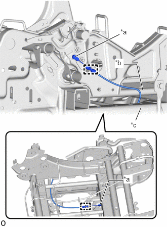
| *a | Cable End |
| *b | Pipe |
| *c | Frame |
Attach the cable clamp and cable end and install the No. 1 seat slide cable assembly LH as shown in the illustration.
- NOTICE:
-
Pass the No. 1 seat slide cable assembly LH between the pipe and frame as shown in the illustartion.
- HINT:
-
-
Install at the middle level of the cable clamp (triple level) side.
72210V
6.INSTALL NO. 1 SEAT NO. 1 TRACK CONTROL CABLE ASSEMBLY LH (for First Row)
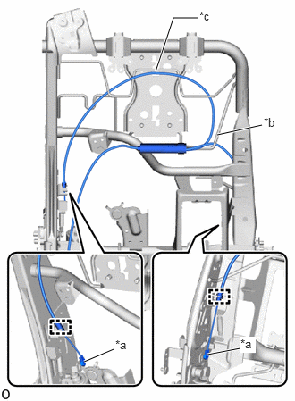
| *a | Cable End |
| *b | Frame Wire |
| *c | Location Tape (Red) |
Attach the cable clamp and cable end and install the No. 1 seat No. 1 track control cable assembly LH as shown in the illustration.
- NOTICE:
-
Pass the No. 1 seat No. 1 track control cable assembly LH through the front side of the frame wire as shown in the illustration.
- HINT:
-
-
Install at the middle level of the cable clamp (triple level) side.
72210W
7.INSTALL NO. 1 SEAT NO. 2 TRACK CONTROL CABLE ASSEMBLY LH (for First Row)
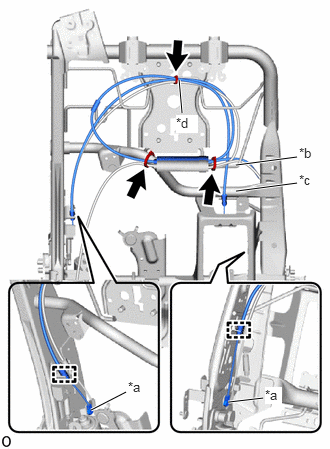
| *a | Cable End |
| *b | Frame Wire |
| *c | Pipe |
| *d | Location Tape (Red) |
Attach the cable clamp and cable end and install the No. 1 seat No. 2 track control cable assembly LH as shown in the illustration.
- NOTICE:
- ·
Pass the No. 1 seat No. 2 track control cable assembly LH through the front side of the frame wire as shown in the illustration.
·Pass the No. 1 seat No. 2 track control cable assembly LH between the pipe and frame wire as shown in the illustartion.
- HINT:
-
-
Install at the middle level of the cable clamp (triple level) side.
| *a | Cut Here |
| *b | 5 mm (0.197 in.) to 10 mm (0.394 in.) |
| *c | Correct |
| *d | Incorrect |
Install 3 new cable ties.
Cut off the end of the cable tie as shown in the illustration.
- HINT:
-
Make sure that the end of the cable tie faces below.
73380D
8.INSTALL REAR SEAT INNER BELT ASSEMBLY
71875Y
9.INSTALL LH SEATBACK RECLINING ADJUSTER INSIDE COVER RH
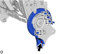
Attach the guide.
Install the LH seatback reclining adjuster inside cover RH with the screw.
71875X
10.INSTALL RECLINING ADJUSTER INSIDE COVER RH
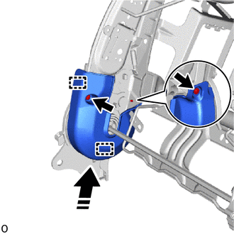

|
Install in this Direction |
Attach the guide as shown in the illustration.
Install the reclining adjuster inside cover RH with the 2 screws.
71H76S
11.INSTALL LH SEATBACK RECLINING ADJUSTER INSIDE COVER LH
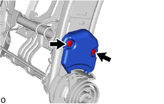
Install the LH seatback reclining adjuster inside cover LH with the 2 clips.
72554E
12.INSTALL NO. 1 RECLINING COVER PROTECTOR LH

Install the No. 1 reclining cover protector LH with the clip.
72554F
13.INSTALL NO. 2 RECLINING COVER PROTECTOR LH
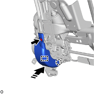
|
|
Install in this Direction |
Attach the claw and guide as shown in the illustration.
Install the No. 2 reclining cover protector LH with the screw.
82168
14.INSTALL NO. 2 SEAT WIRE
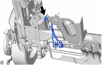
Connect the connector.
Attach the clamp and install the No. 2 seat wire.
79104A
15.INSTALL NO. 1 SEATBACK FRAME SUB-ASSEMBLY LH
Temporarily install the No. 1 seatback frame sub-assembly LH with the 2 bolts A and 2 bolts B.
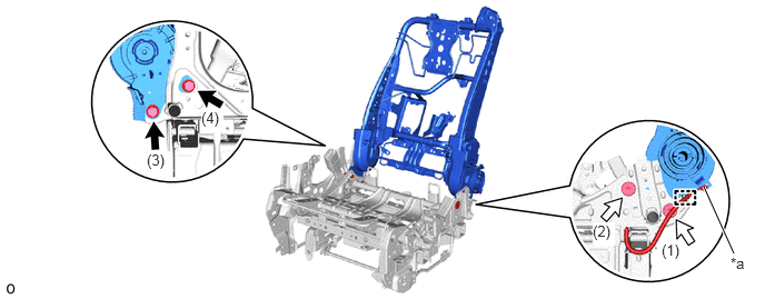
| *a | Cable End | - | - |

|
Bolt A | 
|
Bolt B |
Using a T50 "TORX" socket wrench, tighten the 2 bolts B in the order shown in the illustration.
- Torque:
- 45 N*m (459 kgf*cm, 33 ft.*lbf)
- HINT:
-
Press the center area of No. 1 seatback frame sub-assembly LH to rear side when tightening the bolt.
Tighten the 2 bolts A in the order shown in the illustration.
- Torque:
- 45 N*m (459 kgf*cm, 33 ft.*lbf)
- HINT:
-
Press the center area of No. 1 seatback frame sub-assembly LH to rear side when tightening the bolt.
Attach the cable clamp and cable end.
- HINT:
-
-
Install at the middle level of the cable clamp (triple level) side.
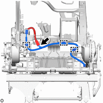
Attach the clamp and connect the connector.
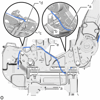
| *a | Leg Side Pipe |
| *b | Cushion Rear Pipe |
| *c | Cushion Front Pipe |
| *d | Bracket |
| *e | Location Tape (Blue) |
Set the cable as shown in the illustration.
- NOTICE:
- ·
Pass the cable under the leg side pipe as shown in the illustration.
·Pass the cable above the cushion rear pipe as shown in the illustration.
·Pass the cable between the cushion front pipe and bracket as shown in the illustration.
71H75F
16.INSTALL REAR NO. 1 LH SEAT RECLINING ADJUSTER INSIDE COVER RH
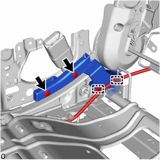
|
|
Install in this Direction |
Install the rear No. 1 LH seat reclining adjuster inside cover RH with the 2 clips.
Attach the clamp.
71H76F
17.INSTALL REAR NO. 1 LH SEAT RECLINING ADJUSTER INSIDE COVER LH
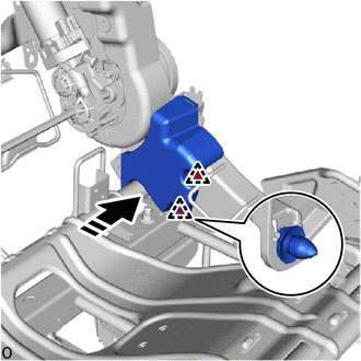
|
|
Install in this Direction |
Attach the clip and install the rear No. 1 LH seat reclining adjuster inside cover LH as shown in the illustration.
73373X
18.INSTALL NO. 1 SEAT NO. 1 SHOULDER BELT COVER LH
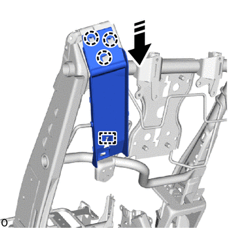
|
|
Install in this Direction |
Attach the hook.
Attach the claw and install the No. 1 seat No. 1 shoulder belt cover LH as shown in the illustration.
73390
19.INSTALL REAR SEAT 3 POINT TYPE BELT ASSEMBLY LH
71879J
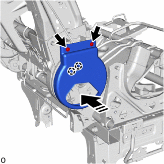
20.INSTALL REAR NO. 1 SEAT INNER RECLINING COVER LH
|
|
Install in this Direction |
Attach the claw.
Install the rear No. 1 seat inner reclining cover LHwith the 2 screws.
73373W
21.INSTALL NO. 1 SEAT NO. 2 SHOULDER BELT COVER LH

| *a | Location Tape (Blue) |
|
|
Install in this Direction |
Attach the claw and install the No. 1 seat No. 2 shoulder belt cover LH as shown in the illustration.
Attach the cables to the No. 1 seat No. 2 shoulder belt cover LH.
71499M
22.INSTALL NO. 1 SEATBACK SPRING DAMPER LH
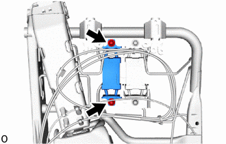
Install the No. 1 seatback spring damper LH with the 2 nuts.
- Torque:
- 14.5 N*m (148 kgf*cm, 11 ft.*lbf)
71499V
23.INSTALL NO. 1 SEATBACK NO. 2 SPRING DAMPER LH
- HINT:
-
Use the same procedure described for the No. 1 seatback spring damper LH.
71695L
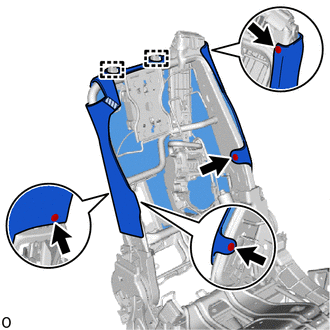
24.INSTALL NO. 1 SEATBACK PROTECTOR LH

|
Fastening Tape |
Attach the guide and install the No. 1 seatback protector LH.
Attach the fastening tape.
Install the 4 clips.
72075C
25.INSTALL LH SEAT RECLINING ADJUSTER ARM SUB-ASSEMBLY
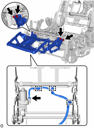
Install the LH seat reclining adjuster arm sub-assembly with the 4 bolts.
- Torque:
- 22 N*m (224 kgf*cm, 16 ft.*lbf)
Connect the connector.
Attach the clamp.
78656K
26.INSTALL REAR SEAT LEGREST COVER LH
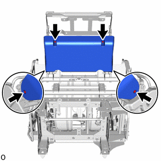
Install the rear seat legrest cover LH with the 4 screws.
78987B
27.INSTALL REAR NO. 1 SEAT NO. 1 FOOTREST COVER LH
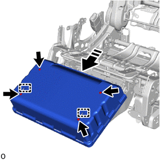
|
|
Install in this Direction |
Attach the hook as shown in the illustration.
Install the rear No. 1 seat No. 1 footrest cover LH with the 4 screws.
87510Y
28.INSTALL REAR NO. 1 SEAT CUSHION HEATER ASSEMBLY LH (w/ Seat Heater System)
29.INSTALL SEAT COVER WIRE
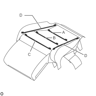
Install the seat cover wire.
- HINT:
- ·
Wire 1000 mm (3.28 ft.) or longer and shaped wire are available as supplied parts.
·For wire 1000 mm (3.28 ft.) or less in length, cut or shape 1000 mm (3.28 ft.) wire into the dimensions shown in the illustration.
·Make sure to read the Precaution section before preparing the wire.
- Dimensions:
A 240 mm (9.45 in.) B 310 mm (1.02 ft.) C 330 mm (1.08 ft.) D 370 mm (1.21 ft.)
- HINT:
-
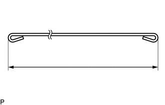
-
The dimensions shown in the illustration are the length.
79012A
30.INSTALL NO. 1 SEAT CUSHION COVER SUB-ASSEMBLY LH
- HINT:
-
When installing a No. 1 seat cushion cover sub-assembly LH, refer to Precaution in order to prevent wrinkles from forming.
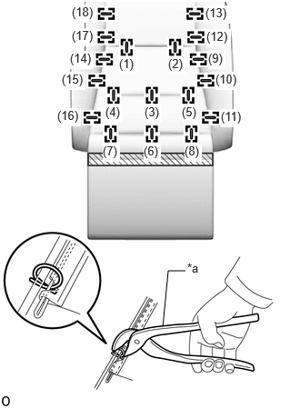
| *a | Hog Ring Pliers |
|
|
Fastening tape |
Attach the fastening tape.
Using hog ring pliers, install the No. 1 seat cushion cover sub-assembly LH with 18 new hog rings in the order shown in the illustration.
- NOTICE:
- ·
Be careful not to damage the No. 1 seat cushion cover sub-assembly LH.
·Be sure to securely install the hog rings as shown in the illustration while preventing wrinkles from forming on the No. 1 seat cushion cover sub-assembly LH.
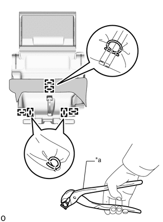
| *a | Hog Ring Pliers |
Using hog ring pliers, install 6 new hog rings.
- NOTICE:
-
Be careful not to damage the No. 1 seat cushion cover sub-assembly LH.
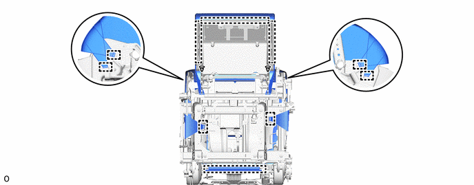
31.INSTALL SEPARATE TYPE REAR SEAT CUSHION COVER WITH PAD
Set the separate type rear seat cushion cover with pad.
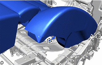
Attach the claw and install the connector of the occupant detection sensor.
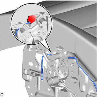
Pass the cable through the pocket.
Attach the hook and install the 2 clips.
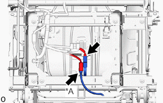
| *A | w/ Seat Heater System |
Connect the connector of occupant detection sensor.
w/ Seat Heater System:
Connect the connector of seat heater.
85861
32.INSTALL SEAT CLIMATE CONTROL ECU (w/ Seat Heater System)
79968W
33.INSTALL LH SEAT REAR NO. 1 SEAT LEG SIDE COVER
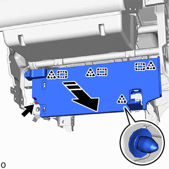
|
|
Install in this Direction |
Attach the clip and guide as shown in the illustration.
Install the LH seat rear No. 1 seat leg side cover with the screw.
71H76N
34.INSTALL LH SEAT RECLINING ADJUSTER INSIDE COVER
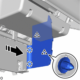
|
|
Install in this Direction |
Attach the clip and claw and install the LH seat reclining adjuster inside cover as shown in the illustration.
72690G
35.INSTALL NO. 2 SEAT CUSHION LOCK RELEASE LEVER ASSEMBLY LH (for Second Row)
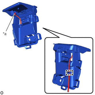
| *a | Cable End |
Attach the cable clamp and cable end.
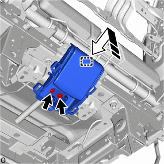
|
|
Install in this Direction |
Attach the hook as shown in the illustration.
Install the No. 2 seat cushion lock release lever assembly LH with the 2 screws.
72345R
36.INSTALL NO. 2 SEAT STAND FRAME CAP LH (for Second Row)
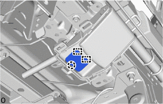
Attach the claw and guide and install the No. 2 seat stand frame cap LH.
79959F
37.INSTALL NO. 1 SEAT LEG COVER LH
for First Row:
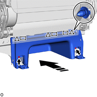
|
|
Install in this Direction |
Attach the clip and guide as shown in the illustration.
Install the No. 1 seat leg cover LH with the 2 screws.
for Second Row:
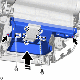
|
|
Install in this Direction |
Attach the claw and guide as shown in the illustration.
Install the No. 1 seat leg cover LH with the 4 screws.
87530
38.INSTALL NO. 1 SEATBACK HEATER ASSEMBLY LH (w/ Seat Heater System)
39.INSTALL SEAT COVER WIRE
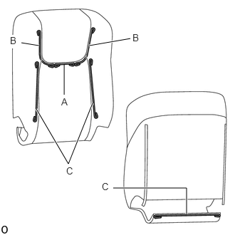
Install the seat cover wire.
- HINT:
- ·
Wire 1000 mm (3.28 ft.) or longer and shaped wire are available as supplied parts.
·For wire 1000 mm (3.28 ft.) or less in length, cut or shape 1000 mm (3.28 ft.) wire into the dimensions shown in the illustration.
·Make sure to read the Precaution section before preparing the wire.
- Dimensions:
A 90 mm (3.54 in.) B 200 mm (7.87 in.) C 300 mm (11.8 in.)
- HINT:
-
-
The dimensions shown in the illustration are the length.
79014B
40.INSTALL NO. 1 SEATBACK COVER SUB-ASSEMBLY LH
- HINT:
-
When installing a No. 1 seatback cover sub-assembly LH, refer to Precaution in order to prevent wrinkles from forming.
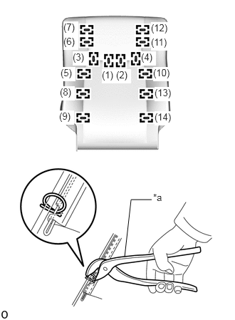
| *a | Hog Ring Pliers |
Using hog ring pliers, install the No. 1 seatback cover sub-assembly LH with 14 new hog rings in the order shown in the illustration.
- NOTICE:
- ·
Be careful not to damage the No. 1 seatback cover sub-assembly LH.
·Be sure to securely install the hog rings as shown in the illustration while preventing wrinkles from forming on the No. 1 seatback cover sub-assembly LH.
41.INSTALL SEPARATE TYPE REAR SEATBACK COVER WITH PAD
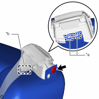
| *a | Hook |
| *b | Guide |
Attach the guide and install the separate type rear seatback cover with pad.
- NOTICE:
-
Be careful not to damage the separate type rear seatback cover with pad.
Install the clip and attach the hook.
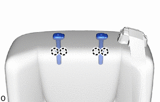
Attach the claw and install the 2 rear seat headrest supports.
w/ Seat Heater System:
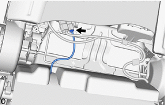
Connect the connector.
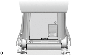
Attach the fastening tape.
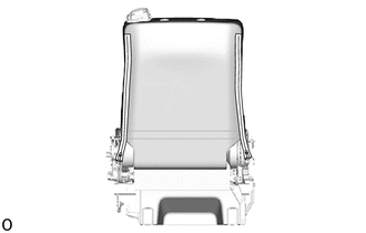
Close the 2 fasteners.
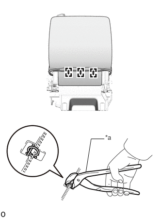
| *a | Hog Ring Pliers |
Using hog ring pliers, install 3 new hog rings.
- NOTICE:
-
Be careful not to damage the No. 1 seatback cover sub-assembly LH.
73390
42.INSTALL REAR SEAT 3 POINT TYPE BELT ASSEMBLY LH (ANCHOR)
72046G
43.INSTALL LH SEAT NO. 1 SEAT NO. 2 TRACK COVER SUB-ASSEMBLY
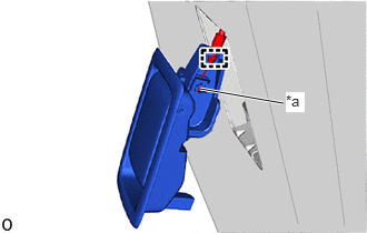
| *a | Cable End |
Attach the cable clamp and cable end.
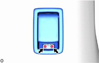
Install the LH seat No. 1 seat No. 2 track cover sub-assembly with the 2 screws.
72345Z
44.INSTALL LH SEAT NO. 1 SEAT NO. 2 STAND FRAME CAP
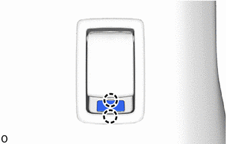
Attach the claw and install the rear seat stand frame cap as shown in the illustration.
73375
45.INSTALL REAR SEAT SHOULDER BELT COVER LH
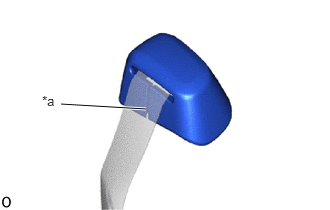
| *a | Slit |
Pass the belt through the slit.
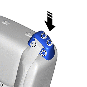
|
|
Install in this Direction |
Attach the claw and install rear seat shoulder belt cover LH as shown in the illustration.
71H75R
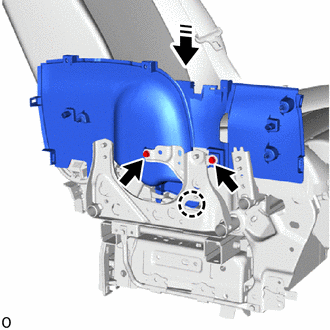
46.INSTALL LH SEAT RECLINING ADJUSTER INSIDE COVER RH
|
|
Install in this Direction |
Attach the claw as shown in the illustration.
Install the LH seat reclining adjuster inside cover RH with the 2 bolts.
- Torque:
- 4.5 N*m (46 kgf*cm, 40 in.*lbf)
72803H
47.INSTALL LH SEAT REAR NO. 1 SEAT ARMREST FRAME SUB-ASSEMBLY RH
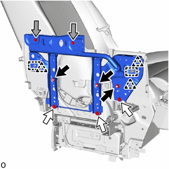
|
|
Nut |
|
|
Bolt A |

|
Bolt B |
Attach the clip and guide.
Install the LH seat rear No. 1 seat armrest frame sub-assembly RH with the 3 bolts A and 3 nuts.
- Torque:
- 16 N*m (163 kgf*cm, 12 ft.*lbf)
Install the 2 bolts B.
- Torque:
- 4.5 N*m (46 kgf*cm, 40 in.*lbf)
66990E
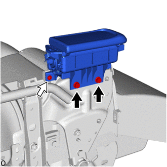
48.INSTALL REAR NO. 1 SEAT CUP HOLDER ASSEMBLY LH
|
|
Bolt |
|
|
Screw |
Install the rear No. 1 seat cup holder assembly LH with the 2 bolts.
- Torque:
- 4.5 N*m (46 kgf*cm, 40 in.*lbf)
Install the screw.
71826C
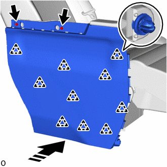
49.INSTALL REAR SEAT CUSHION MOULDING LH
|
|
Install in this Direction |
Attach the clip as shown in the illustration.
Install the rear seat cushion moulding LH with the 2 bolts.
- Torque:
- 4.5 N*m (46 kgf*cm, 40 in.*lbf)
71866D
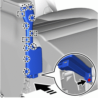
50.INSTALL LH SEAT REAR NO. 1 SEAT COVER BEZEL
|
|
Install in this Direction |
Attach the claw and guide as shown in the illustration.
Install the LH seat rear No. 1 seat cover bezel with the screw.
71H74
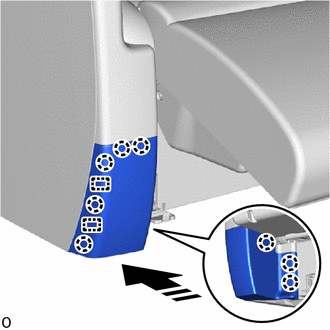
51.INSTALL REAR SEAT LOWER CUSHION SHIELD LH (for Second Row)
|
|
Install in this Direction |
Attach the claw and guide and install the rear seat lower cushion shield LH as shown in the illustration.
71848W
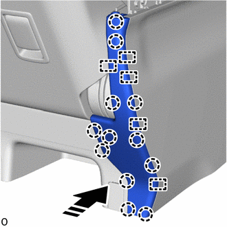
52.INSTALL LH SEAT NO. 1 SEAT ADJUSTER COVER CAP
for First Row:
|
|
Install in this Direction |
Attach the claw and guide and install the LH seat No. 1 seat adjuster cover cap as shown in the illustration.
for Second Row:
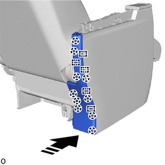
|
|
Install in this Direction |
Attach the claw and guide and install the LH seat No. 1 seat adjuster cover cap as shown in the illustration.
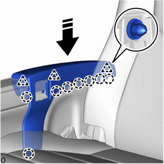
72840K
53.INSTALL REAR NO. 1 SEAT ARMREST ASSEMBLY LH
|
|
Install in this Direction |
Attach the claw and clip and install the rear No. 1 seat armrest assembly LH as shown in the illustration.
84923
54.INSTALL REAR POWER SEAT SWITCH
78060C
55.INSTALL NO. 1 SEAT SIDE TABLE ASSEMBLY (for First Row, RH Side)
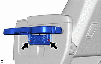
Install the No. 1 seat side table assembly with the 2 nuts.
- Torque:
- 14.5 N*m (148 kgf*cm, 11 ft.*lbf)
72046F
56.INSTALL LH SEAT NO. 1 SEAT NO. 1 TRACK COVER SUB-ASSEMBLY (for First Row)
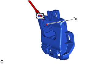
| *a | Cable End |
Attach the cable clamp and cable end.
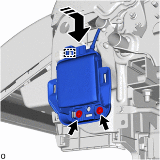
|
|
Install in this Direction |
Attach the hook as shown in the illustration.
Install the LH seat No. 1 seat No. 1 track cover sub-assembly with the 2 screws.
71H76P
57.INSTALL LH SEAT RECLINING ADJUSTER INSIDE COVER LH
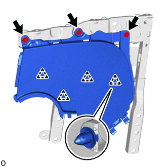
Attach the clip and install the LH seat reclining adjuster inside cover LH.
Install the 3 bolts.
- Torque:
- 4.5 N*m (46 kgf*cm, 40 in.*lbf)
72804E
58.INSTALL LH SEAT REAR NO. 1 SEAT ARMREST FRAME SUB-ASSEMBLY LH
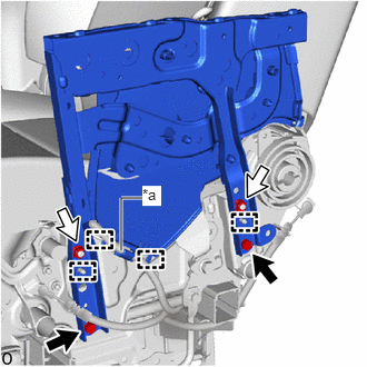
| *a | Location Tape (Blue) |
|
|
Bolt |
|
|
Nut |
Attach the guide.
Attach the cable to the LH seat rear No. 1 seat armrest frame sub-assembly LH.
Install the LH seat rear No. 1 seat armrest frame sub-assembly LH with the 2 nuts and 2 bolts.
- Torque:
- 16 N*m (163 kgf*cm, 12 ft.*lbf)
71844J
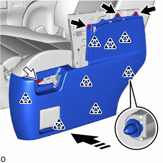
59.INSTALL REAR NO. 1 SEAT NO. 2 RECLINING COVER LH
|
|
Bolt |
|
|
Screw |
|
|
Install in this Direction |
Attach the clip and install the rear No. 1 seat No. 2 reclining cover LH as shown in the illustration.
Install the 3 bolts.
- Torque:
- 4.5 N*m (46 kgf*cm, 40 in.*lbf)
Install the screw.
72C45
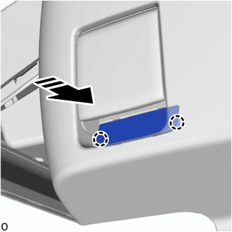
60.INSTALL LH SEAT NO. 1 SEAT NO. 3 STAND FRAME CAP (for First Row)
|
|
Install in this Direction |
Attach the claw and install the LH seat No. 1 seat No. 3 stand frame cap as shown in the illustration.
71849L
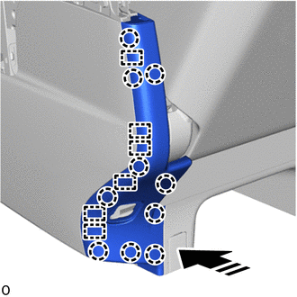
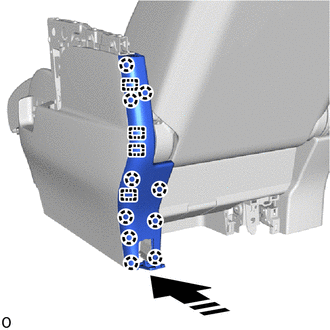
61.INSTALL NO. 1 SEAT ADJUSTER COVER CAP LH
for First Row:
|
|
Install in this Direction |
Attach the claw and guide and install the No. 1 seat adjuster cover cap LH as shown in the illustration.
for Second Row:
|
|
Install in this Direction |
Attach the claw and guide and install the No. 1 seat adjuster cover cap LH as shown in the illustration.
71324R
62.INSTALL REAR NO. 1 SEAT CUSHION LH (for First Row)
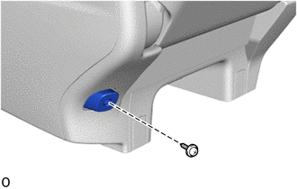
Install the rear No. 1 seat cushion LH with the screw.
72890C
63.INSTALL LH SEAT NO. 1 SEAT ARMREST ASSEMBLY
|
|
Install in this Direction |
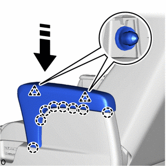
Attach the claw and clip and install the LH seat No. 1 seat armrest assembly.
72345Y
64.INSTALL LH SEAT NO. 1 SEAT NO. 1 STAND FRAME CAP
|
|
Install in this Direction |
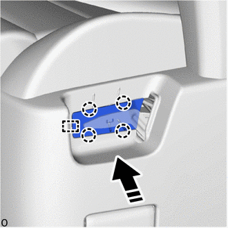
Attach the claw and guide and install the LH seat No. 1 seat No. 1 stand frame cap.
72526J
65.INSTALL NO. 1 SEAT RECLINING ADJUSTER RELEASE HANDLE LH
|
|
Install in this Direction |
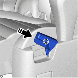
No. 1 seat reclining adjuster release handle LH