LIGHTING (EXT) LIGHTING SYSTEM(w/ Headlight ECU) B242E Open in IG Circuit
DESCRIPTION
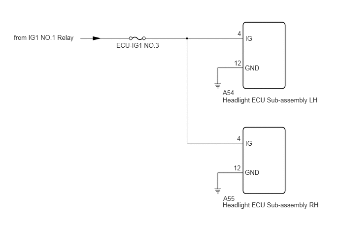
The headlight ECU sub-assembly operates using the power source voltage input from the IG terminal and ECUB terminal.
The IG terminal power source voltage is supplied by turning the IG1 NO. 1 relay to ON.
The headlight ECU sub-assembly receives engine switch on (IG) signals from the main body ECU (multiplex network body ECU) via CAN communication, compares the engine switch on (IG) signal and the power source voltage supply condition of the IG terminal and monitors the result.
| DTC No. | Detection Item | DTC Detection Condition | Trouble Area | DTC Output from | Note |
|---|---|---|---|---|---|
| B242E | Open in IG Circuit | Detection condition:
The engine switch is on (IG) Malfunction status:
When the IG terminal power source voltage is 0 V (engine switch off), IG ON signals from the main body ECU (multiplex network body ECU) via CAN communication are continuously received Malfunction duration:
10 seconds or more |
·
Headlight ECU sub-assembly LH ·
Headlight ECU sub-assembly RH ·
Harness or connector |
HL AutoLeveling
HL AutoLeveling (Sub) |
- |
WIRING DIAGRAM
CAUTION / NOTICE / HINT
- NOTICE:
- ·
Inspect the fuses for circuits related to this system before performing the following procedure.
·If the headlight ECU sub-assembly LH has been replaced, it is necessary to synchronize the vehicle information and initialize the headlight ECU sub-assembly LH.
·When replacing the headlight ECU sub-assembly LH, always replace it with a new one. If a headlight ECU sub-assembly LH which was installed to another vehicle is used, the information stored in it will not match the information from the vehicle and a DTC may be stored.
PROCEDURE
Connect the GTS to the DLC3.
Turn the engine switch on (IG).
Turn the GTS on.
Enter the following menus: Body Electrical / HL AutoLeveling or HL AutoLeveling (Sub) / Clear DTCs.
Clear the DTCs.
- Body Electrical > HL AutoLeveling > Clear DTCs
- 50002 361
- Body Electrical > HL AutoLeveling (Sub) > Clear DTCs
- 50002 414
- Result:
Proceed to NEXT
NEXT
Connect the GTS to the DLC3.
Turn the engine switch on (IG).
Wait 10 seconds or more.
Turn the GTS on.
Enter the following menus: Body Electrical / HL AutoLeveling or HL AutoLeveling (Sub) / Trouble Codes.
Check for DTCs.
- Body Electrical > HL AutoLeveling > Trouble Codes
- 50001 361
- Body Electrical > HL AutoLeveling (Sub) > Trouble Codes
- 50001 414
- OK:
DTC B242E is not output.
- Result:
Result Proceed to OK A NG (DTC output from headlight ECU sub-assembly LH) B NG (DTC output from headlight ECU sub-assembly RH) C
A
B
C
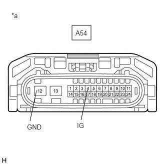
| *a | Front view of wire harness connector
(to Headlight ECU Sub-assembly LH) |
Disconnect the headlight ECU sub-assembly LH connector.
Measure the voltage according to the value(s) in the table below.
- Standard Voltage:
Tester Connection Switch Condition Specified Condition A54-4 (IG) - Body ground Engine switch on (IG) 11 to 14 V
Measure the resistance according to the value(s) in the table below.
- Standard Resistance:
Tester Connection Condition Specified Condition A54-12 (GND) - Body ground Always Below 1 Ω
- Result:
Proceed to OK NG
OK
NG
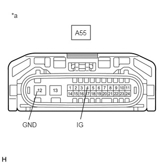
| *a | Front view of wire harness connector
(to Headlight ECU Sub-assembly RH) |
Disconnect the headlight ECU sub-assembly RH connector.
Measure the voltage according to the value(s) in the table below.
- Standard Voltage:
Tester Connection Switch Condition Specified Condition A55-4 (IG) - Body ground Engine switch on (IG) 11 to 14 V
Measure the resistance according to the value(s) in the table below.
- Standard Resistance:
Tester Connection Condition Specified Condition A55-12 (GND) - Body ground Always Below 1 Ω
- Result:
Proceed to OK NG
OK
NG