LIGHTING (EXT) HEADLIGHT ASSEMBLY(for Halogen Headlight) REASSEMBLY
CAUTION / NOTICE / HINT
- HINT:
- ·
Use the same procedure for the RH and LH sides.
·The procedure listed below is for the LH side.
PROCEDURE

 85669
1.INSTALL HEADLIGHT LEVELING MOTOR BASE PACKING (w/ Headlight Leveling)
85669
1.INSTALL HEADLIGHT LEVELING MOTOR BASE PACKING (w/ Headlight Leveling)
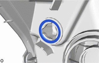
Install a new headlight leveling motor base packing.
85662
2.INSTALL HEADLIGHT LEVELING MOTOR LH (w/ Headlight Leveling)


|
Tighten in this Direction |
Set the tip of the aiming screw of the headlight leveling motor LH.
Tighten the aiming screw of the headlight leveling motor LH the same number of rotations recorded when removing it to connect the headlight leveling motor LH.

|
|
Install in this Direction |
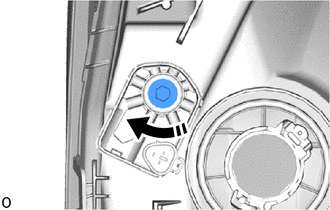
Insert the headlight leveling motor LH.
Turn the headlight leveling motor LH clockwise to install it.
- HINT:
-
For the headlight assembly RH, turn the headlight leveling motor RH counterclockwise to install it.
|
|
Tighten in this Direction |
Tighten the aiming screw 10 rotations.
81194A
3.INSTALL HEADLIGHT PROTECTOR LH (w/ Protector)

|
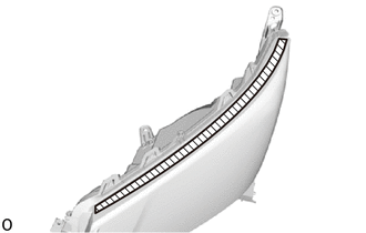
Area to Clean |
Clean the application area of the headlight protector LH shown in the illustration.
- NOTICE:
-
Remove any remaining double-sided tape, and then clean and degrease the area.
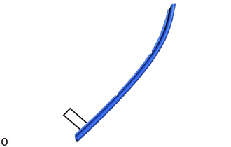
Remove approximately 30 mm (1.18 in.) of the peeling paper from a new headlight protector LH.
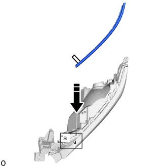
| *a | Application Start Position |
|
|
Set in this Direction |
Align the angle of the headlight protector LH with the application start position, and then set only the part with peeling paper removed into place.
Press the set portion of the part with your finger to secure it.
- NOTICE:
-
Do not slide your finger horizontally, as doing so may stretch the part unnecessarily.
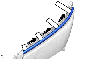
|
|
Install in this Direction |
Align with the curve and set only the part where the peeling type tape was removed from into place.
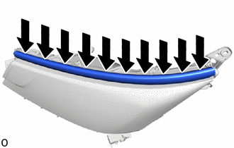

|
Press Here |
Press the set portion of the part with your finger to secure it.
- NOTICE:
-
Do not slide your finger horizontally, as doing so may stretch the part unnecessarily.
81510D
4.INSTALL FRONT TURN SIGNAL LIGHT BULB
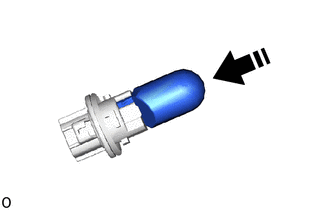
|
|
Install in this Direction |
Install the front turn signal light bulb to the bulb socket.
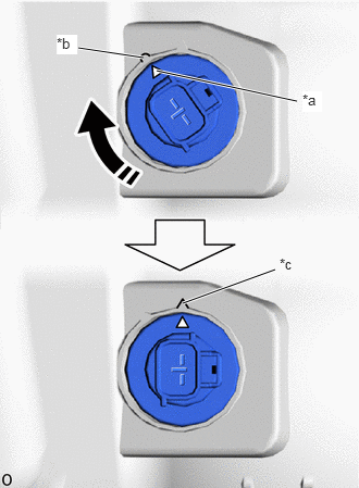
| *a | Matchmark |
| *b | Unlock Position Mark |
| *c | Lock Position Mark |
|
|
Turn in this Direction |
Align the matchmark of the bulb socket with the unlock position mark, and then turn the bulb socket clockwise until the lock position mark to install the bulb socket.
81610F
5.INSTALL CLEARANCE LIGHT BULB (w/o Daytime Running Light)
|
|
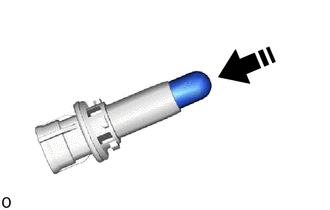
Install in this Direction |
Install the clearance light bulb to the bulb socket.
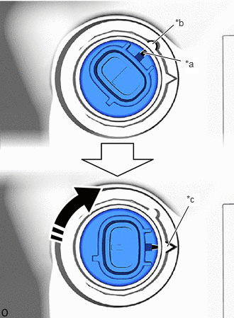
| *a | Matchmark |
| *b | Unlock Position Mark |
| *c | Lock Position Mark |
|
|
Turn in this Direction |
Align the matchmark of the bulb socket with the unlock position mark, and then turn the bulb socket clockwise until the lock position mark to install the bulb socket.
81510J
6.INSTALL DAYTIME RUNNING LIGHT BULB (w/ Daytime Running Light)
|
|
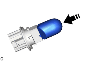
Install in this Direction |
Install the daytime running light bulb to the bulb socket.
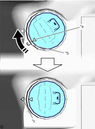
| *a | Matchmark |
| *b | Unlock Position Mark |
| *c | Lock Position Mark |
|
|
Turn in this Direction |
Align the matchmark of the bulb socket with the unlock position mark, and then turn the bulb socket clockwise until the lock position mark to install the bulb socket.
81110B
7.INSTALL NO. 1 HEADLIGHT BULB
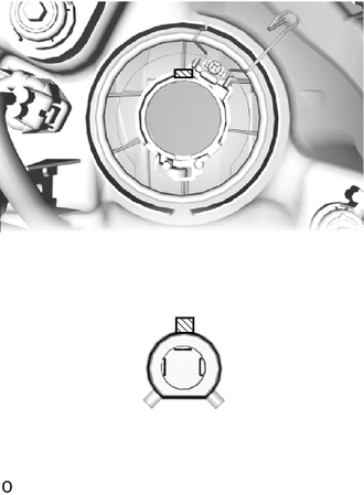
Align the shaded area of the No. 1 headlight bulb shown in the illustration with the shaded area of the headlight and insert the No. 1 headlight bulb into the headlight.
- NOTICE:
-
Do not touch the glass part of the No. 1 headlight bulb.
|
|
Lock in this Direction |
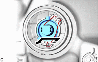
Lock the set spring by moving it in the direction indicated by the arrow in the illustration.
81144C
8.INSTALL HEADLIGHT SOCKET COVER
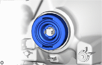
Install the headlight socket cover.